Ventilation system and ventilation fan with lamp
- Summary
- Abstract
- Description
- Claims
- Application Information
AI Technical Summary
Benefits of technology
Problems solved by technology
Method used
Image
Examples
first embodiment
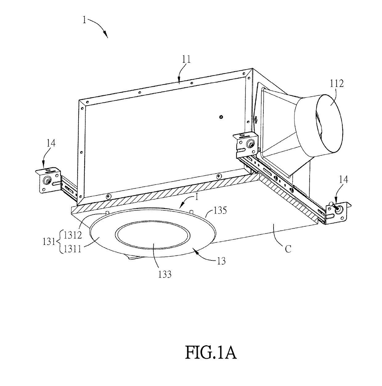
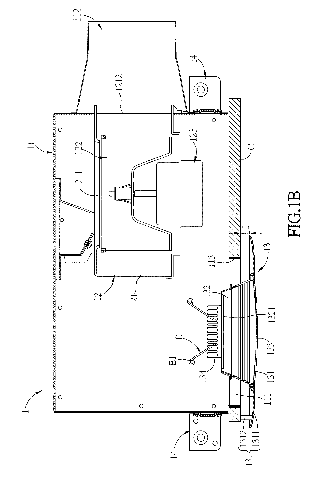
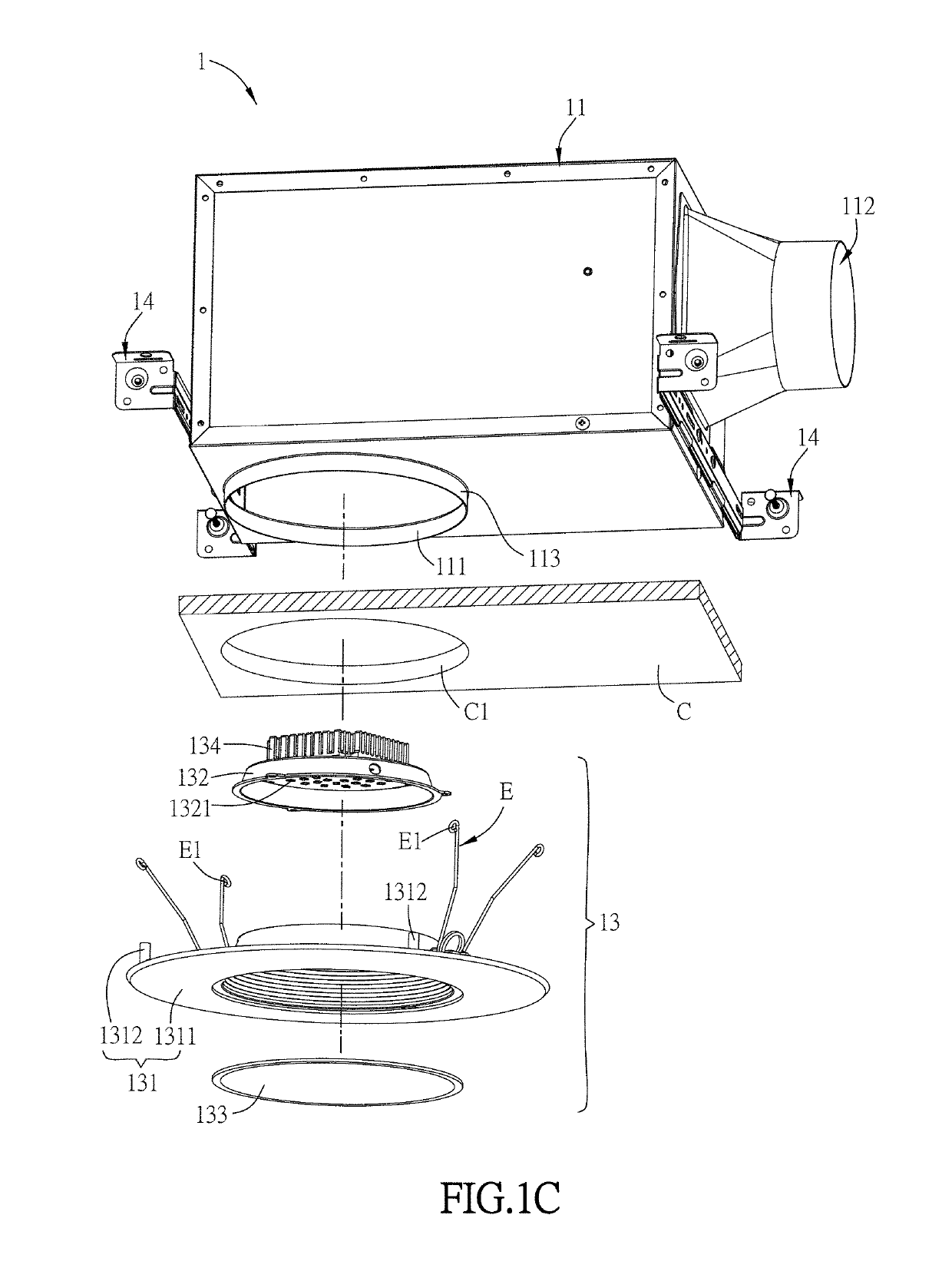
[0092]FIG. 1A is a schematic diagram of a ventilation fan with a lamp of the invention, FIG. 1B is a sectional diagram of the ventilation fan in FIG. 1A, and FIG. 1C is an exploded diagram of the ventilation fan in FIG. 1A. As shown in FIGS. 1A, 1B, 1C, the ventilation fan with the lamp 1 (abbreviated to the ventilation fan 1 hereinafter) is installed to a ceiling C including an installation opening C1. For the clarity of the figure to facilitate the illustration of the ventilation fan of this embodiment, only a part of the ceiling is shown. Herein, the ventilation fan 1 includes a housing 11, a fan module 12 and a lamp module 13. Moreover, the ventilation fan 1 of this embodiment further includes two installation brackets 14, which can be connected to the housing 11 and ceiling C by screwing, for example, to fix the housing 11 to the ceiling C. However, this invention is not limited thereto.
[0093]In this embodiment, the housing 11 is approximately a six-sided box structure and incl...
second embodiment
[0103]FIG. 3C is a schematic sectional diagram of a ventilation fan of another embodiment of the invention. As shown in FIG. 3C, this embodiment is approximately the same as the above second embodiment, and the main difference therebetween is that the lens 133a is disposed between the lamp cover 131 and the base 132 and inside the housing 11. Certainly, the lens 133a also can be disposed at the first opening 111 so that a part of the lens 133a is disposed inside the housing and another part of the lens 133a is exposed from the housing 11.
[0104]FIG. 4 is a schematic sectional diagram of a ventilation fan with a lamp of the third embodiment of the invention. As shown in FIG. 4, the ventilation fan 1b of this embodiment is approximately the same as the first embodiment, and the main difference therebetween is that the size of the housing 11a of this embodiment is less than that of the housing 11 of the above embodiment so that at least half volume of the fan module 12 is on the project...
sixth embodiment
[0130]FIG. 7A is a schematic diagram of a ventilation fan with a lamp of the invention, and FIG. 7B is a sectional diagram of the ventilation fan of FIG. 7A.
[0131]The ventilation fan 2c of this embodiment is mostly the same as the ventilation fan 2. Different from the ventilation fan 2, the housing 21c of the ventilation fan 2c further includes a bottom plate 216, which connects to the side wall 217, and the bottom plate 216 is configured with a second opening 211 instead from the first opening 219. The second opening 211 is aligned with the installation opening C1. The configuration of the second opening 211 of the bottom plate 216 allows to install the housing 21c of the ventilation fan 2c on the ceiling C.
[0132]To be noted, the housing 21c is a rectangular box, containing the top plate 218, the side wall 217 and the bottom plate 216, with a second opening 211 formed on the bottom plate 216. The top plate 218 is parallel to the bottom plate 216. The top plate 218, the side wall 21...
PUM
 Abstract
Description
Claims
Application Information
 - R&D
- Intellectual Property
- Life Sciences
- Materials
- Tech Scout
- Unparalleled Data Quality
- Higher Quality Content
- 60% Fewer Hallucinations
Browse by: Latest US Patents, China's latest patents, Technical Efficacy Thesaurus, Application Domain, Technology Topic, Popular Technical Reports.
© 2025 PatSnap. All rights reserved.Legal|Privacy policy|Modern Slavery Act Transparency Statement|Sitemap|About US| Contact US: help@patsnap.com


