
Mouse

a mouse and mouse body technology, applied in the field of mouse, can solve the problems of limited mouse volume reduction, and achieve the effect of reducing the height between the base and the cover plate, reducing the volume of the mouse, and reducing the touch feeling of the user when pressing

Inactive Publication Date: 2019-06-04
PRIMAX ELECTRONICS LTD
View PDF9 Cites 0 Cited by
  • Summary
  • Abstract
  • Description
  • Claims
  • Application Information

AI Technical Summary

Benefits of technology

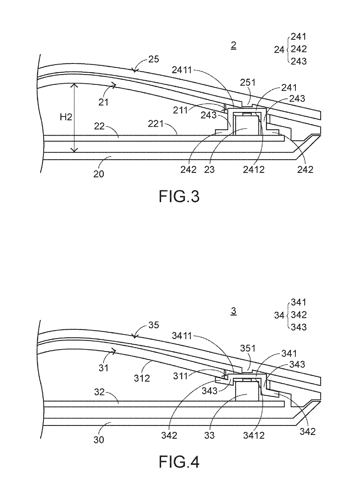
[0007]In a preferred embodiment, the present invention provides a mouse, including a base, a cover plate, a circuit board, a button switch, an elastic cover, and an upper cover. The cover plate is located on the base and covers the base. The cover plate is provided with a hole. The circuit board is disposed on the base and located between the base and the cover plate. The button switch is disposed on the circuit board and extends into the hole. The elastic cover covers the button switch, and extends into the hole together with the button switch, so as to prevent the button switch from being exposed out of the hole. The upper cover covers the cover plate, and the upper cover is capable of oscillating relative to the cover plate to abut against the elastic cover, so as to trigger the button switch.
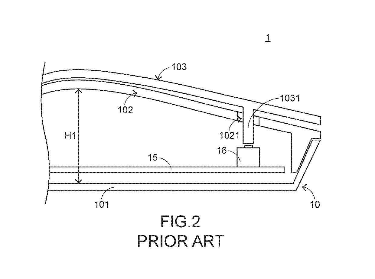
[0009]In brief, in the mouse of the present invention, by means of configuration of the button switch being close to the cover plate, the height between the base and the cover plate may be reduced, so as to reduce the volume of the mouse. In the mouse of the present invention, by covering the elastic cover onto the button switch, the touch feeling of a user when pressing the upper cover is improved due to the elasticity of the elastic cover. At the same time, the elastic cover may also block a noise generated when the button switch is triggered, so as to provide a function of noise reduction. In addition, the elastic cover covering the button switch may even provide functions of dust prevention and waterproofing, and prevent a phenomenon of electrostatic discharge (ESD).

Problems solved by technology

However, with the development of mice, users require a mouse to have a light and thin appearance.
However, the reduction in the volume of the mouse is still limited.

Method used


Image

  • Mouse
  • Mouse
  • Mouse

Examples


Embodiment Construction

[0014]In view of puzzlement caused by the conventional technologies, the present invention provides a mouse capable of resolving the problems of the conventional technologies. First, the structure of the mouse of the present invention is described. Referring to FIG. 3, FIG. 3 is a schematic sectional view of a local structure of the mouse of the present invention according to a first preferred embodiment. A mouse 2 of the present invention includes a base 20, a cover plate 21, a circuit board 22, a button switch 23, an elastic cover 24, and an upper cover 25. The cover plate 21 is located on the base 20 and covers the base 20. The cover plate 21 is provided with a hole 211 and the hole 211 corresponds to a button (that is, a left button or a right button of the mouse). The circuit board 22 is disposed on the base 20 and located between the base 20 and the cover plate 21. The button switch 23 corresponding to the button is disposed on the circuit board 22 and is electrically connecte...


PUM


Abstract

The present invention relates to a mouse, including a base, a cover plate provided with a hole, a circuit board, a button switch, an elastic cover, and an upper cover. The cover plate covers the base, and the circuit board is disposed on the base and located between the base and the cover plate. The button switch is disposed on the circuit board. The elastic cover covers the button switch, and extends into the hole together with the button switch, so as to prevent the button switch from being exposed out of the hole. The upper cover covers the cover plate, and the upper cover is capable of oscillating relative to the cover plate to abut against the elastic cover, so as to trigger the button switch.

Description

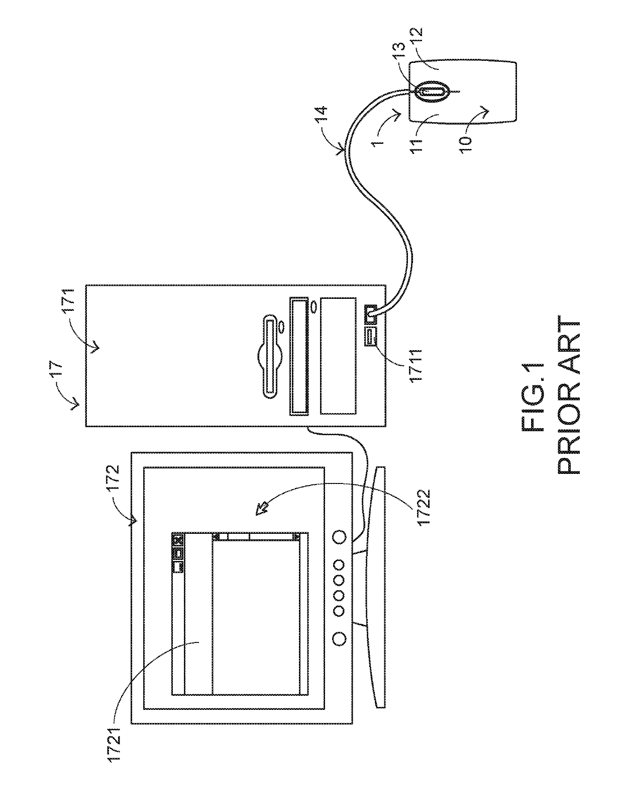
FIELD OF THE INVENTION[0001]The present invention relates to an input device, and in particular, to a mouse capable of controlling movement of a cursor.BACKGROUND OF THE INVENTION[0002]Commonly seen computer peripheral input devices include a mouse, a keyboard, a trackball, and so on. Since the mouse may be held by a user with a palm to control movement of a cursor and accords with operation habits of most users, the mouse has become the most common input device.[0003]First, the structure and function of a conventional mouse are described. Referring to FIG. 1, FIG. 1 is a schematic structural diagram of a conventional mouse being connected to a computer system. A computer system 17 includes a computer host 171 and a computer screen 172. The computer host 171 is separately connected to a mouse 1 and the computer screen 172, and the computer host 171 is provided with a connection port 1711. The computer screen 172 may display a window 1721 and a cursor 1722. The function of the mouse ...

Claims


Application Information

Patent Timeline
Patent Type & Authority Patents(United States)
IPC IPC(8): H01H13/10G06F3/0354H05K3/30H01H13/14H05K1/18H01H13/04
CPCG06F3/03543H01H13/04H01H13/10H01H13/14H05K2201/2018H05K3/301H05K2201/0133H05K2201/10053H05K1/181
Inventor HSIAO, SHAO-LUNCHANG, CHIA-YUANCHU, CHUN-LIN
Owner PRIMAX ELECTRONICS LTD
Learn More