Measuring system and measuring method

a measurement system and measuring method technology, applied in the field of measuring systems, can solve the problems of low measurement accuracy requirements, inability to meet many highly precise measurements, and stringent measurement accuracy requirements, and achieve the effect of improving measurement accuracy and simplifying structur

Active Publication Date: 2018-04-05
CARL ZEISS IND MESSTECHN GMBH
View PDF1 Cites 5 Cited by
  • Summary
  • Abstract
  • Description
  • Claims
  • Application Information

AI Technical Summary

Benefits of technology

[0015]It is an object to provide an optical measuring system of the type mentioned above which, in contrast to the aforementioned handheld measuring systems from the prior

Problems solved by technology

However, the extremely stringent requirements for the measurement accuracy that these measuring systems are intended to deliver often count against the usability of such a mobile measuring system.
In principle, these methods have some shortcomings, however, which result in them currently not yet being suitable for many highly precise measurements but only being used for measurements which have lower requirements for the measurement accuracy.
Such active markers which are integrated in the handheld measuring tool have the disadvantage that, due to the development of heat caused by them, they give rise to material expansions which may result in measurement errors.
Such measurement errors cannot be disregarded at all in optical measurement technology.
Since the user inevitably exerts a force for this purpose, the magnitude and direction of which are unknown, the probe head can be readily deformed, shak

Method used


Image

  • Measuring system and measuring method
  • Measuring system and measuring method
  • Measuring system and measuring method

Examples


Embodiment Construction

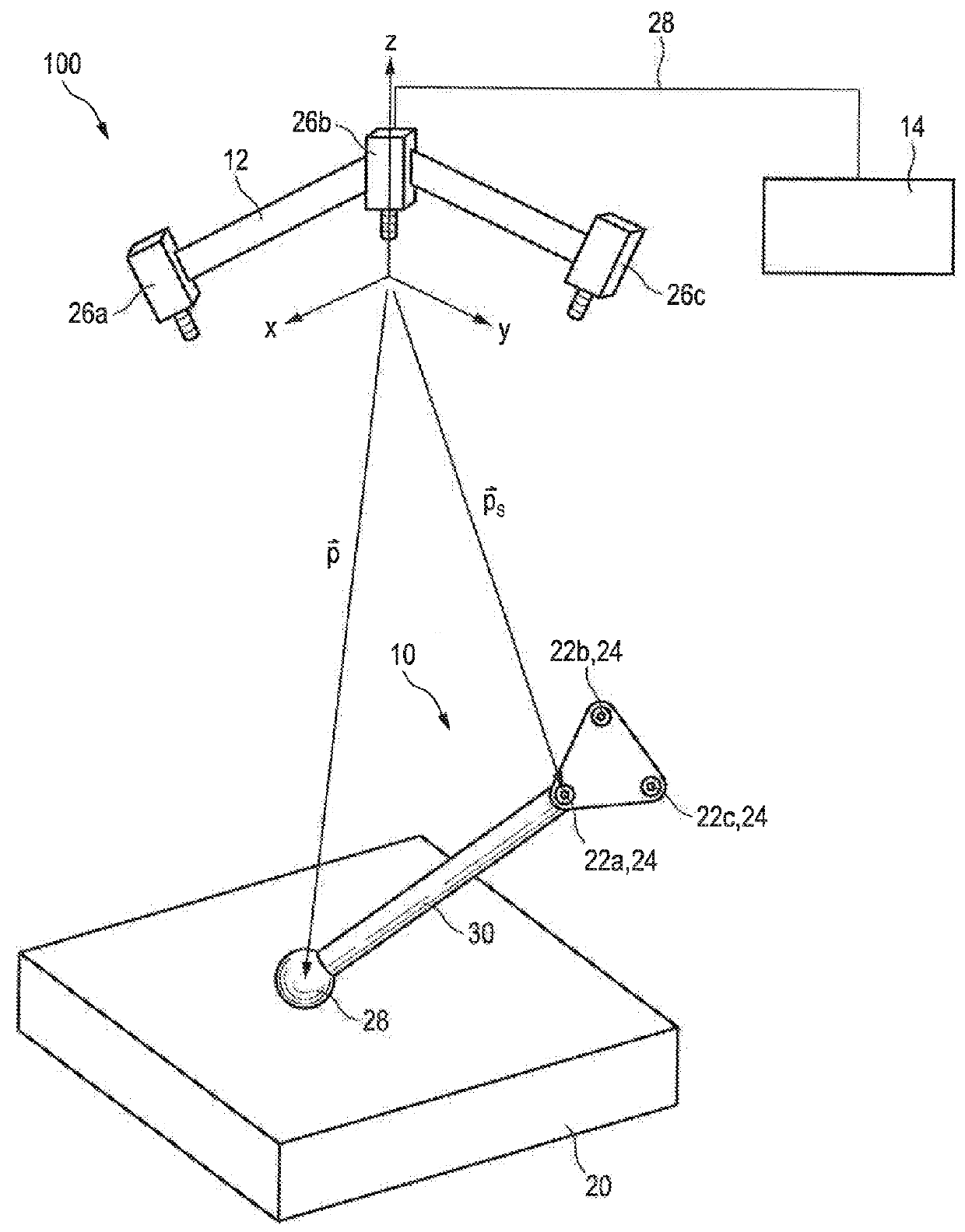
[0067]FIG. 1 shows a simplified representation of an exemplary embodiment of the measuring system. The measuring system is designated as a whole by the reference numeral 100 therein. Part of the measuring system 100 is a measuring tool which is designated by the reference numeral 10.

[0068]In addition to the measuring tool 10, the measuring system comprises a camera system 12 and also an evaluation and control unit 14.

[0069]The measuring tool 10 is used to scan a workpiece 20 in a tactile manner. This scanning can be carried out manually, that is to say in a handheld manner, or automatically with the aid of a suitable machine, e.g. a robot. During scanning of the workpiece 20, the position of the measuring tool 10 is captured with the aid of the tracking system consisting of the camera system 12 and the evaluation and control unit 14. The position is preferably captured continuously or at a scanning frequency, which is preferably 200 Hz or greater. The position is captured based on t...


PUM


Abstract

A measuring system having a measuring tool which comprises a probe body and an optical marker, a camera for recording image data of the measuring tool, and an evaluation and control unit which is configured to evaluate the image data recorded by the camera and use the data to determine spatial position coordinates of the optical marker. The evaluation and control unit is also configured to calculate the deformation of the measuring tool due to external mechanical loading acting on the measuring tool, and to determine spatial position coordinates of the probe body based on the spatial position coordinates of the optical marker and the calculated deformation.

Description

CROSS-REFERENCE TO RELATED APPLICATION[0001]This application claims Convention priority of German patent application 10 2016 118 620.1, filed on Sep. 30, 2016. The entire content of this priority application is incorporated herein by reference.BACKGROUND OF THE INVENTION[0002]The present disclosure relates to a measuring system having a measuring tool which comprises a probe body and an optical marker, having a camera for recording image data of the measuring tool, and having an evaluation and control unit which is configured to evaluate the image data recorded by the camera and to use said data to determine spatial position coordinates of the optical marker.[0003]The present disclosure further relates to a corresponding measuring method as well as to a computer program product, which comprises a program code that is configured to perform the method when it is run on a computer for controlling the aforementioned measuring system.[0004]An exemplary measuring system of the above-menti...

Claims


Application Information

Patent Timeline
IPC IPC(8): G01B11/00G06T7/73
CPCG01B11/007G06T7/73G06T2207/30204G01B5/008G01B11/005G01B21/042G01B5/016G01B11/002
Inventor HELD, TOBIAS
Owner CARL ZEISS IND MESSTECHN GMBH
Why Eureka
Try Eureka