Optical fiber monitoring system

a technology of optical fiber and monitoring system, applied in the direction of fiber optic/optical waveguide devices, testing of fiber optics/machines, instruments, etc., can solve the problem of taking a lot of time and effort, and achieve the effect of facilitating the check of the health of inter-building optical fibers

Active Publication Date: 2018-05-10
HITACHI METALS LTD +1
View PDF0 Cites 0 Cited by
  • Summary
  • Abstract
  • Description
  • Claims
  • Application Information

AI Technical Summary

Benefits of technology

[0013]According to an embodiment of the invention, an optical fiber monitoring system can be provided that facilitates the check of the health of the inter-building optical fibers.

Problems solved by technology

In inspecting the health of inter-building optical fibers, however, it is necessary to send workers to two buildings respectively connected by the inter-building optical fibers to check the existence of faults by measuring e.g. optical loss of inter-building optical fibers which are going to be used, so that it takes a lot of time and efforts.

Method used


Image

  • Optical fiber monitoring system
  • Optical fiber monitoring system
  • Optical fiber monitoring system

Examples


embodiment

[0023]An embodiment of the invention will be described below in conjunction with the appended drawings.

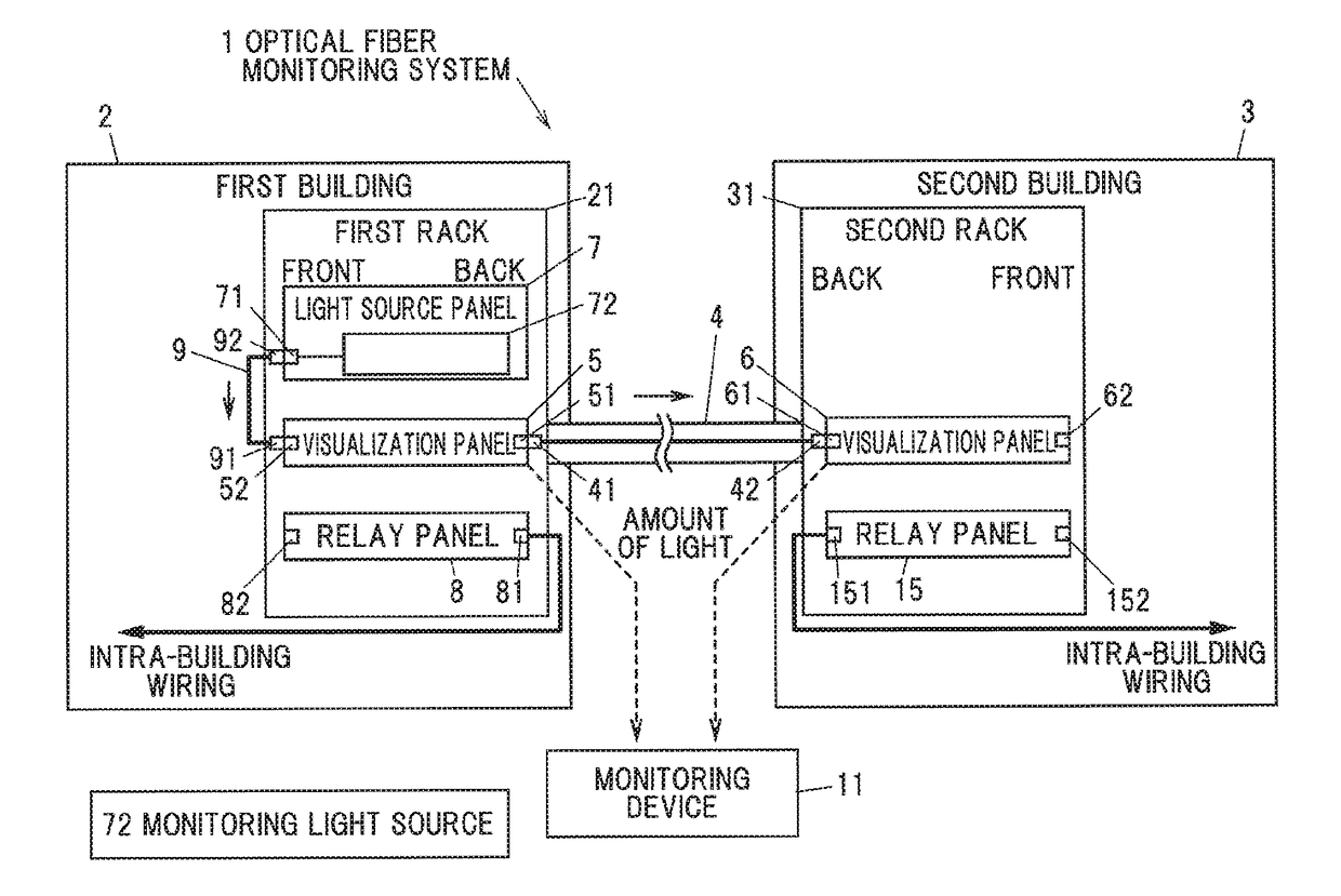
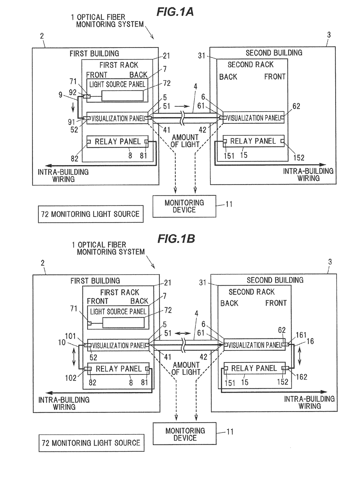
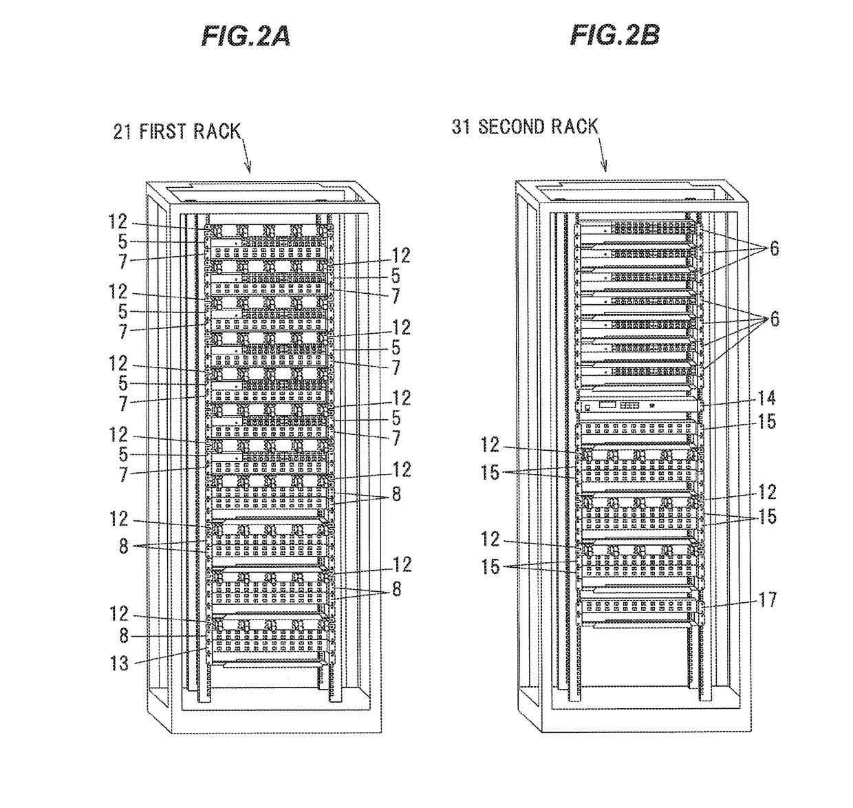
[0024]FIGS. 1A and 1B are schematic configuration diagrams illustrating an optical fiber monitoring system in the present embodiment, wherein FIG. 1A shows a state in which an inter-building optical fiber is not used and FIG. 1B shows a state in which the inter-building optical fiber is used. FIG. 2A is a diagram illustrating an appearance of a first rack and FIG. 2B is a diagram illustrating an appearance of a second rack.

[0025]As shown in FIGS. 1A to 2B, an optical fiber monitoring system 1 monitors inter-building optical fibers 4 connecting a first building 2 to a second building 3. The first building 2 and the second building 3 are, e.g., data centers (or office buildings containing data centers).

[0026]The first building 2 is communicably connected to the second building 3 by plural inter-building optical fibers 4. In this example, the two buildings 2 and 3 are connected by one...


PUM


Abstract

An optical fiber monitoring system monitors an inter-building optical fiber connecting a first building and a second building. The optical fiber monitoring system includes a first visualization panel provided in the first building and optically connected to an one end of the inter-building optical fiber, a second visualization panel provided in the second building and optically connected to an other end of the inter-building optical fiber, and a monitoring light source provided in the first building to input a monitoring light into the inter-building optical fiber. The first visualization panel includes a first photosensor that partially leaks the monitoring light inputted into the inter-building optical fiber from the monitoring light source and detects an amount of a leaked light. The second visualization panel includes a second photosensor that partially leaks a light from the inter-building optical fiber and detects amount of a leaked light.

Description

[0001]The present application is based on Japanese patent application No. 2016-215932 filed on Nov. 4, 2016, the entire contents of which are incorporated herein by reference.BACKGROUND OF THE INVENTION1. Field of the Invention[0002]The invention relates to an optical fiber monitoring system.2. Description of the Related Art[0003]Inter-building optical fibers (optical fiber cables) are laid between buildings of data center, etc., and fiber-optic communication is performed between the buildings through the inter-building optical fibers.[0004]Since the inter-building optical fibers are routed in outdoor environments, faults such as local bend or wire break occur due to wind and rain, etc. Thus, the health (existence of faults) of inter-building optical fibers is regularly inspected. The health of inter-building optical fibers is also inspected when the status of inter-building optical fibers are changed from not in use (standby) to in use.[0005]JP 2015 / 200707 discloses a prior art tha...

Claims


Application Information

Patent Timeline
Patent Type & Authority Applications(United States)
IPC IPC(8): G01M11/00
CPCG01M11/33G01M11/31
Inventor SUZUKI, KANAKOHIRANO, KOKIOHKOSHI, MIKIOOHNUKI, WATARUNAKATANI, YOSHIHIRONISHIKAWA, TAKAOSUZUKI, TOSHIYUKISAKAI, TOSHIO
Owner HITACHI METALS LTD
Why Eureka
Try Eureka