Eureka AIR delivers breakthrough ideas for toughest innovation challenges, trusted by R&D personnel around the world.

Device and method for testing the plausibility of signals of a rotary encoder

a technology of rotary encoder and plausibility test, which is applied in the direction of measurement devices, instruments, sensor output conversion, etc., can solve problems such as errors in the calculation of angle of rotation, and achieve the effect of testing the plausibility of amplitude differences particularly quickly and with little technical complexity

Active Publication Date: 2018-06-21
ROBERT BOSCH GMBH
View PDF5 Cites 5 Cited by
  • Summary
  • Abstract
  • Description
  • Claims
  • Application Information

AI Technical Summary

Benefits of technology

The present invention provides a method for directly measuring the amplitude difference between the sine and cosine signals of a rotating machine without the need for complex estimation methods. This allows for a faster and more efficient measurement. Additionally, the method includes a maximum value and minimum value determination device that can quickly test the plausibility of the amplitude difference.

Problems solved by technology

If such a sine signal and such a cosine signal have different amplitudes, this may, for example, result in an error in the calculation of the angle of rotation when calculating the angle of rotation, i.e., the angular position, by means of an arctangent.

Method used


Image

  • Device and method for testing the plausibility of signals of a rotary encoder
  • Device and method for testing the plausibility of signals of a rotary encoder
  • Device and method for testing the plausibility of signals of a rotary encoder

Examples


Embodiment Construction

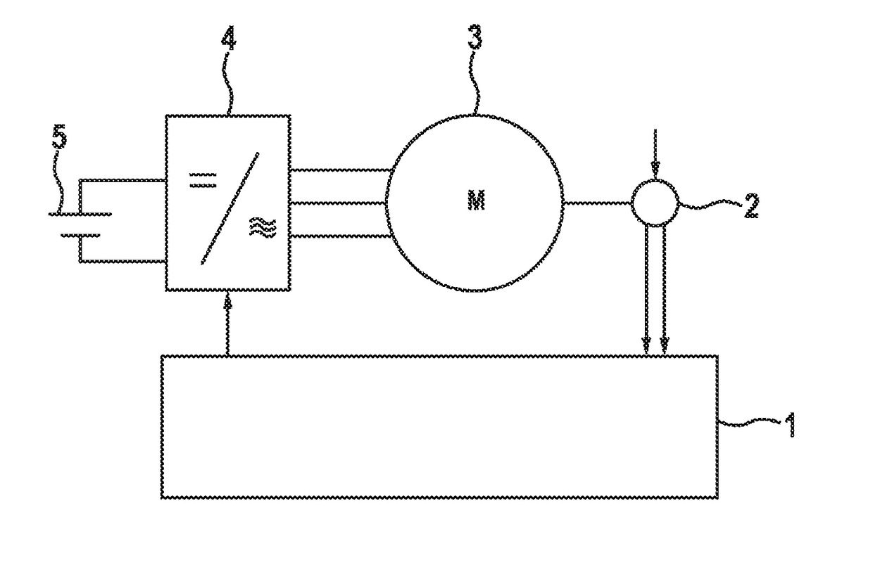
[0026]FIG. 1 shows a schematic block diagram of an electrical drive system according to one embodiment. An electric machine 3 is fed by an electrical power source 5 via a rectifier 4. For example, the electrical power source 5 may be a traction battery of an electric vehicle. The electric machine 3 may, for example, be a permanently excited synchronous machine, an electrically excited synchronous machine, or an asynchronous machine. In addition, other electric machines are also generally possible. The embodiment depicted here of a three-phase electric machine 3 constitutes only one exemplary embodiment. In addition, electric machines having a number of phases differing from three are also possible. The rectifier 4 converts the electrical power provided by the electrical power source 5 and provides the converted electrical power for controlling the electric machine 3. The control of the electric machine 3 may be carried out based on specifications or control signals from a control de...


PUM


Abstract

The invention relates to a device and a method for testing the plausibility of signals of a rotary encoder. The device is formed with: a sine signal-providing device (11) designed to provide a sine signal (51) of the rotary encoder (12); a cosine signal-providing device (12) designed to provide a cosine signal (52) of the rotary encoder (12); a calculation device (14) designed to form a calculation signal (53) based on the sine signal (51) and the cosine signal (52); a maximum value-determining device (16) designed to determine a maximum value of the calculation signal (53); a minimum value-determining device (18) designed to determine a minimum value of the calculation signal (53); a determining device (20) designed to determine a differential signal (56) as or based on a value of a difference between the determined maximum value and the determined minimum value, and which differential signal indicates an amplitude difference between an amplitude of the sine signal (51) and an amplitude of the cosine signal (52); and a plausibility device (22) designed to test the plausibility of the sine signal (51) and the cosine signal (52), in the event that the differential signal (56) falls within a predetermined region.

Description

BACKGROUND OF THE INVENTION[0001]The present invention relates to a device and a method for testing the plausibility of signals of a rotary encoder, in particular for an angle of rotation of a rotor of an electric machine. In particular, the present invention relates to a device and a method for testing the plausibility of the output signals of a rotary encoder, for example, of a resolver.[0002]Electric and hybrid vehicles are becoming increasingly important. For controlling permanently-excited synchronous machines (PSM) and electrically excited synchronous machines (ESM) as are used in such vehicles, knowledge of the rotor position angle of such machines is required. Furthermore, for controlling asynchronous machines (ASM), knowledge of the electrical frequency of the drive is necessary. Various types of sensors may be used for ascertaining the rotor position angle and the electrical frequency. For example, sensors based on the eddy-current effect, resolvers, or digital angle senso...

Claims


Application Information

Patent Timeline
Patent Type & Authority Applications(United States)
IPC IPC(8): G01D18/00G01D5/20
CPCG01D18/00G01D5/20G01D5/24461G01B7/30
Inventor LECHNER, BENJAMINZIRKEL, DANIELRAICHLE, DANIELUNGERMANN, MICHAEL
Owner ROBERT BOSCH GMBH
Why Eureka
Eureka Blog
Learn More