Method and apparatus for channel state information reporting

a channel state and information reporting technology, applied in the field of radio communications, can solve the problems that cannot be solved regarding the reduction of resources occupied, and achieve the effects of improving system performance, improving resource occupied, and improving the throughput of downlink services

Active Publication Date: 2018-06-28
SAMSUNG ELECTRONICS CO LTD
View PDF3 Cites 3 Cited by
  • Summary
  • Abstract
  • Description
  • Claims
  • Application Information

AI Technical Summary

Benefits of technology

[0035]In the schemes provided according to the present disclosure, by precoding CSI-RSs, system performance can be improved, and resources occupied by the CSI-RSs can be largely saved in practical implementations, so that more downlink physical resources can be used for physical downlink shared channel (PDSCH) transmission, and thus throughput of downlink services is improved. Since the schemes would not change traditional systems much, thus system compatibility will not be affected, and they can be implemented simply and efficiently.

Problems solved by technology

Thus, it is an issue yet to be solved regarding how to reduce resources occupied by CSI-RSs as many as possible.

Method used


Image

  • Method and apparatus for channel state information reporting
  • Method and apparatus for channel state information reporting
  • Method and apparatus for channel state information reporting

Examples


embodiment 1

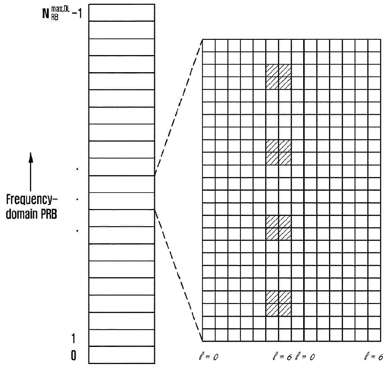
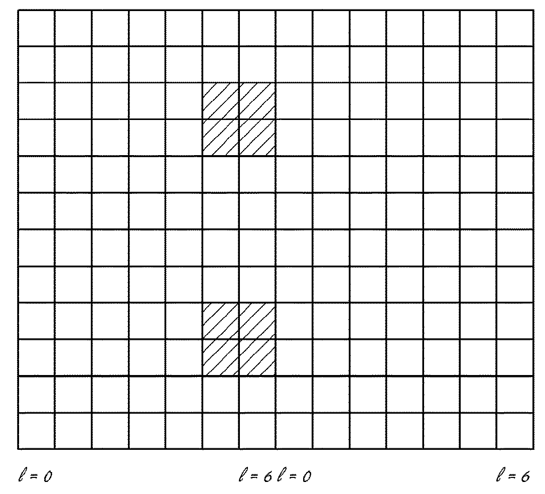
[0056]In this embodiment, a base station configures two sets of CSI-RSs for a UE, in which one set of CSI-RSs is not precoded, and the other is precoded. When the UE measures CSI of the second set of CSI-RSs, it needs to use CSI obtained by measuring the first set of CSI-RSs. For example, based on RI information of CSI obtained by measuring the first set of CSI-RSs, the UE may determine the number of valid CSI-RS ports in the second set of CSI-RSs, so that to measure CSI on the valid CSI-RS ports. To be specific, the UE may obtain a first set of periodic CSI based on measurement of the first set of periodic CSI-RSs, and report the first set of periodic CSI to the base station. Based on the first set of periodic CSI reported by the UE, the base station transmits the second set of CSI-RSs to the UE. The UE obtains a second set of periodic CSI based on measurement of the first set of periodic CSI reported by the UE and the second set of CSI-RSs transmitted from the base station, and th...

embodiment 2

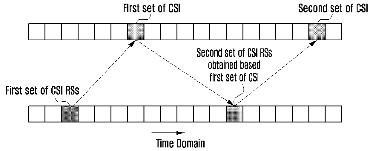
[0069]In this embodiment, a base station configures multiple sets of CSI-RSs for a UE, and different CSI-RSs are precoded using different precoding matrixes. During periodic CSI reporting, the UE first measures the multiple sets of CSI-RSs, selects one or more sets of CSI-RSs (e.g., selecting CSI-RSs with the best receiving performance), and sends an index or indexes of the one or multiple sets of CSI-RSs selected to the base station, which is referred to as a first set of periodic CSI. Subsequent CSI is obtained by measuring CSI-RSs having the index or indexes reported by the UE to the base station, and then the UE reports obtained CSI to the base station, which is referred to as a second set of periodic CSI. During aperiodic CSI reporting, an index or indexes of one or more sets of CSI-RSs selected by the UE is referred to as a first set of aperiodic CSI, and CSI reporting obtained based on the one or more sets of CSI-RSs is referred to as a second set of aperiodic CSI. The second...


PUM


Abstract

The present disclosure provides a method for reporting channel state information (CSI). a first set of channel state information-reference signals (CSI-RSs) sent from a base station is measured to obtain a first set of CSI, and the first set of CSI obtained is reported to the base station. A second set of CSI-RSs sent from the base station is measured based on the first set of CSI to obtain a second set of CSI, and the second set of CSI obtained is reported to the base station, in which the second set of CSI-RSs is precoded CSI-RSs determined based on the first set of CSI.

Description

TECHNICAL FIELD[0001]The present disclosure relates to radio communications and in particular to a method and an apparatus for channel state information reporting in a multi-antenna radio communication system.BACKGROUND ART[0002]In a long term evolution advanced (LTE-A) system, to improve throughput of cells and eliminate interference between subscribers, each cell may be configured with 16, 32, 64, or more transmitting antennas to perform beam shaping. A base station configures channel state information reference signals (CSI-RSs) for each user equipment (UE). Each UE uses the CSI-RSs to measure channel state information (CSI) of a channel, and then provides feedback to the base station. Since before the 3rd Generation Partnership Project (3GPP) release 12, a CSI-RS design is made based on the actual number of physical antennas, and up to 8 ports are involved in a CSI-RS before 3GPP release 12, therefore, each physical resource block may occupy up to 8 resource units, as shown in F...

Claims


Application Information

Patent Timeline
Patent Type & Authority Applications(United States)
IPC IPC(8): H04W24/08H04L5/00H04B7/06H04W24/10
CPCH04W24/08H04L5/0048H04L5/0057H04B7/0632H04W24/10H04W88/08H04B7/0626H04B7/0634H04B7/0456H04B7/06H04B7/0417
Inventor FU, JINGXINGLI, YINGYANGWANG, YI
Owner SAMSUNG ELECTRONICS CO LTD
Why Eureka
Try Eureka