Plunger structure and plunger pump

Inactive Publication Date: 2018-12-20
NINGBO LUTENG PRECISION MACHINERY
View PDF5 Cites 2 Cited by
  • Summary
  • Abstract
  • Description
  • Claims
  • Application Information

AI Technical Summary

Problems solved by technology

The solid plunger requires many materials and has high production cost.
Moreover, the solid structure causes a heavy overall weight, which results in greater friction between the plunger and the plunger pump during working, reducing the working efficiency of the plunger pump.
The open hollow plunger is easily deformed during the production process, and under a working state, the plunger body is subjected to a high-temperature and humid environment so that the inner wall is prone to rust to damage the plunger body, thus the open hollow plunger has short service life, and therefore has

Method used


Image

  • Plunger structure and plunger pump
  • Plunger structure and plunger pump

Examples


Embodiment Construction

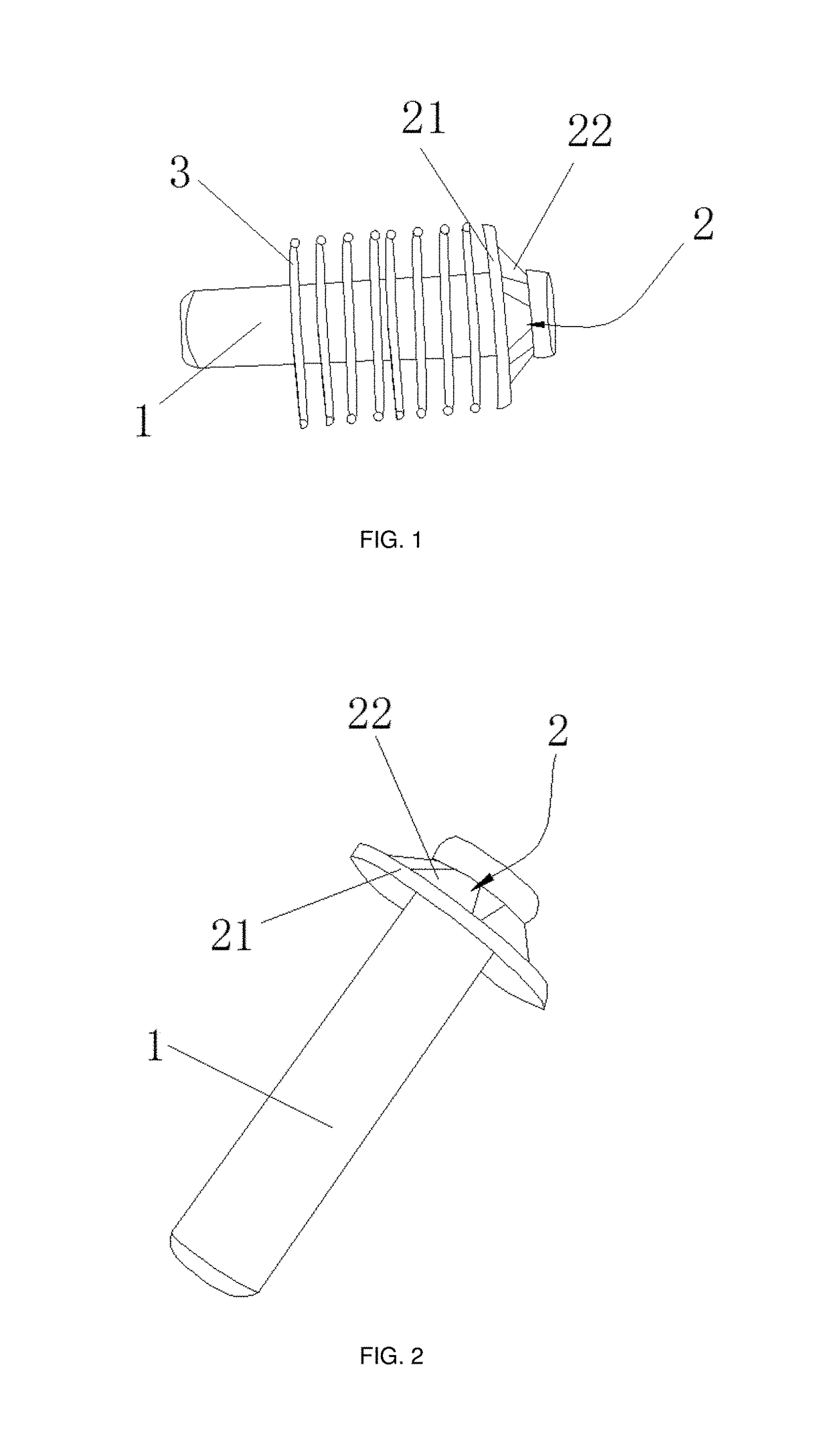
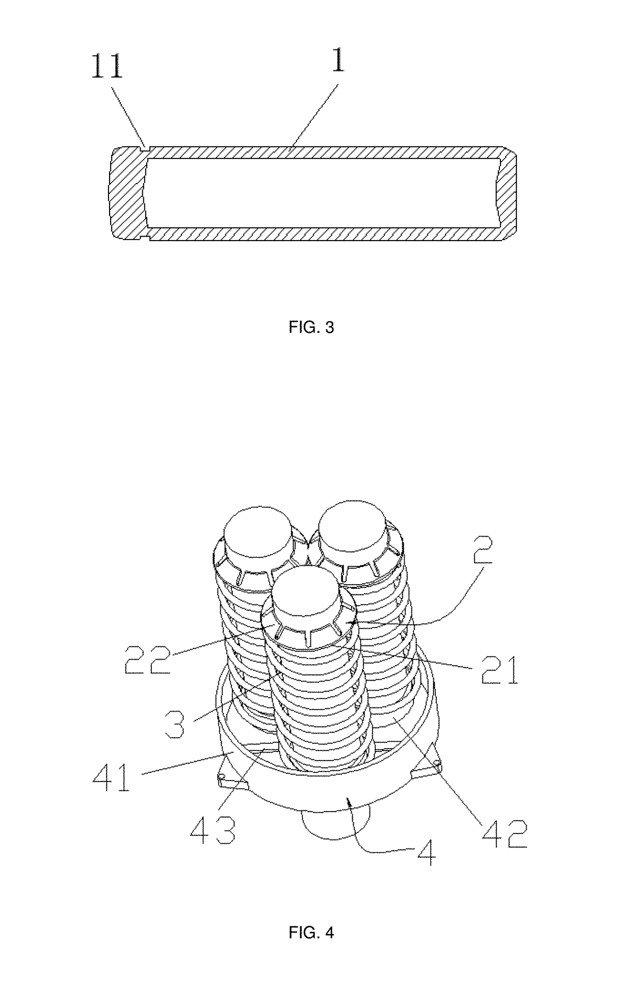
[0030]Various technical solutions of the disclosed technology will be described below with reference to the accompanying drawings. The implementations described are some, but not all, of the implementations consistent with the disclosed and claimed technology. Other implementations obtained by those of ordinary skill in the art in light of the implementations of the disclosed technology without inventive efforts fall within the scope of the present disclosure as claimed.

[0031]In the description of the present disclosure, it should be noted that orientation or positional relations indicated by the terms such as “center”, “up”, “down”, “left”, “right”, “vertical”, “horizontal”, “inside”, “outside”, etc. are the orientation or positional relations shown based on the figures, and these terms are intended only to facilitate the description of the present disclosure and simplify the description, but not intended to indicate or imply that the referred devices or elements must be in a parti...


PUM


Abstract

A plunger structure and a plunger pump are provided, relating to the technical field of plunger pumps. In one exemplary implementation, the plunger structure may comprise a plunger body with both ends closed, an engagement groove disposed at the top of the plunger body, a plunger cap fixedly connected to the engagement groove, and/or an elastic member having one end fixedly disposed within the plunger cap. The plunger body may be sheathed in the elastic member. According to other aspects, a top end of the plunger body may be exposed out from the plunger cap, an engagement groove that is depressed inwardly may be formed in a circumferential direction of the top of the plunger body, an inside of the plunger body may be in a cavity structure, and/or the plunger body may be an integrally molded part.

Description

CROSS-REFERENCE TO RELATED APPLICATIONS[0001]This application claims benefit / priority to Chinese Patent Application No. 201710470921.8, filed Jun. 20, 2017, published as ______, and entitled “Plunger Structure and Plunger Pump,” the contents of which are herein incorporated by reference in their entirety.BACKGROUNDField[0002]The present disclosure relates to the technical field of plunger pumps, and in particular to a plunger structure (plunger piston structure) and a plunger pump (plunger piston pump).Description of the Related Art[0003]In industrial manufacturing and daily life, the cleaning and removal of impurities from a device or an article is generally performed by using a high-pressure water gun. Among them, in the high-pressure washer industry, a power component of the washer mostly employs a plunger pump. For the plunger pump, normal operation of a body is achieved by causing a change of the sealed volume depending on a reciprocating movement of a plunger in a cylinder bor...

Claims


Application Information

Patent Timeline
IPC IPC(8): F04B53/14F04B53/10F04B35/04F04B17/03
CPCF04B53/14F04B53/1077F04B35/04F04B17/03F04B49/06F04B49/10F04B53/00F04B1/0408F04B1/124
Inventor YU, SHIDING
Owner NINGBO LUTENG PRECISION MACHINERY
Why Eureka
Try Eureka