Contingency Autonomous Yaw Control for a Wind Turbine

a technology of wind turbines and autonomous yaw control, which is applied in the direction of machines/engines, mechanical equipment, greenhouse gas reduction, etc., can solve the problems of wind turbines being subjected to increased loads, wind turbine components being subject to significant fatigue cycles, and no way to operate the yaw system

Active Publication Date: 2019-04-04
GENERAL ELECTRIC CO
View PDF14 Cites 8 Cited by
  • Summary
  • Abstract
  • Description
  • Claims
  • Application Information

AI Technical Summary

Benefits of technology

[0007]In one aspect, the present disclosure is directed to a yaw system of a wind turbine having contingency autonomous control capabilities. The yaw system includes a plurality of yaw system components configured to change an angle of a nacelle of the wind turbine relative to an incoming wind direction. The plurality of yaw system components includes an auxiliary power supply comprising a brake power control device (e.g. such as a variable frequency drive), a b

Problems solved by technology

There are instances, however, where the controller may be offline, such as for example, adverse grid or weather events (e.g. typhoons, hurricanes, etc.) as well as regular maintenance.
If the controller is offline, there is no way to operate the yaw system.
Without the yaw system, the wind turbine may be subjected to

Method used


Image

  • Contingency Autonomous Yaw Control for a Wind Turbine
  • Contingency Autonomous Yaw Control for a Wind Turbine
  • Contingency Autonomous Yaw Control for a Wind Turbine

Examples


Embodiment Construction

[0032]Reference now will be made in detail to embodiments of the invention, one or more examples of which are illustrated in the drawings. Each example is provided by way of explanation of the invention, not limitation of the invention. In fact, it will be apparent to those skilled in the art that various modifications and variations can be made in the present invention without departing from the scope or spirit of the invention. For instance, features illustrated or described as part of one embodiment can be used with another embodiment to yield a still further embodiment. Thus, it is intended that the present invention covers such modifications and variations as come within the scope of the appended claims and their equivalents.

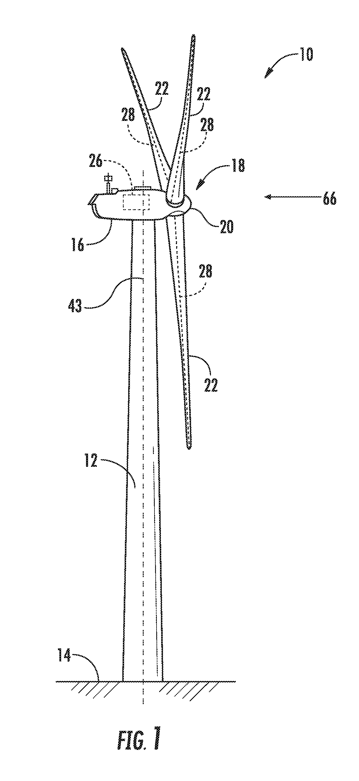
[0033]Referring now to the drawings, FIG. 1 illustrates a perspective view of one embodiment of a wind turbine 10 according to the present disclosure. As shown, the wind turbine 10 generally includes a tower 12 extending from a support surface 14, a nacelle...


PUM


Abstract

A yaw system of a wind turbine having contingency autonomous control capabilities includes a plurality of yaw system components configured to change an angle of a nacelle of the wind turbine relative to an incoming wind direction. The plurality of yaw system components includes an auxiliary power supply comprising a brake power control device, a braking unit coupled to the brake power control device, at least two energy storage devices coupled to the braking unit, a plurality of yaw drive mechanisms communicatively coupled to the auxiliary power supply via a communication link, and a controller configured to implement a protective control strategy for the yaw system in response to one of the yaw system components experiencing a failure. Each of the yaw drive mechanisms includes a yaw power control device.

Description

FIELD[0001]The present disclosure relates in general to wind turbine, and more particularly to contingency autonomous yaw control for wind turbines.BACKGROUND[0002]Wind power is considered one of the cleanest, most environmentally friendly energy sources presently available, and wind turbines have gained increased attention in this regard. A modern wind turbine typically includes a nacelle fixed atop a tower, a generator and a gearbox housed with the nacelle, and a rotor configured with the nacelle having a rotatable hub with one or more rotor blades. The rotor blades capture kinetic energy of wind using known airfoil principles. The rotor blades transmit the kinetic energy in the form of rotational energy so as to turn a shaft coupling the rotor blades to a gearbox, or if a gearbox is not used, directly to the generator. The generator then converts the mechanical energy to electrical energy that may be deployed to a utility grid.[0003]At least some known nacelles include a yaw syst...

Claims


Application Information

Patent Timeline
IPC IPC(8): F03D7/04F03D17/00F03D7/02F03D9/11F03D9/17F03D80/70
CPCF03D7/047F03D7/0204F05B2270/1074F03D17/00Y02E10/72Y02E60/16Y02E70/30F03D7/02F03D9/11F03D9/17F03D80/70F03D7/042
Inventor DHARMADHIKARI, PARAG RAMESHCHANDRASCHNETZKA, HAROLD ROBERT
Owner GENERAL ELECTRIC CO
Why Eureka
Try Eureka