Pneumatic tire

a technology of pneumatic tires and treads, applied in the field of pneumatic tires, can solve the problems of water shedding performance tending to decrease, and achieve the effect of preventing water shedding performance reduction and maintaining resistance to uneven wear

Active Publication Date: 2019-06-27
TOYO TIRE & RUBBER CO LTD
View PDF0 Cites 0 Cited by
  • Summary
  • Abstract
  • Description
  • Claims
  • Application Information

AI Technical Summary

Benefits of technology

[0005]The problem is therefore to provide a pneumatic tire that permits suppression of reduction in water shedding performance that might otherwise occur in accompaniment to wear and yet also makes it possible for resistance to uneven wear to be maintained.

Problems solved by technology

With pneumatic tires, it so happens that water shedding performance tends to decrease due to the lowering of the void fraction within the region of the contact patch that occurs in accompaniment to wear.

Method used


Image

  • Pneumatic tire
  • Pneumatic tire
  • Pneumatic tire

Examples


Embodiment Construction

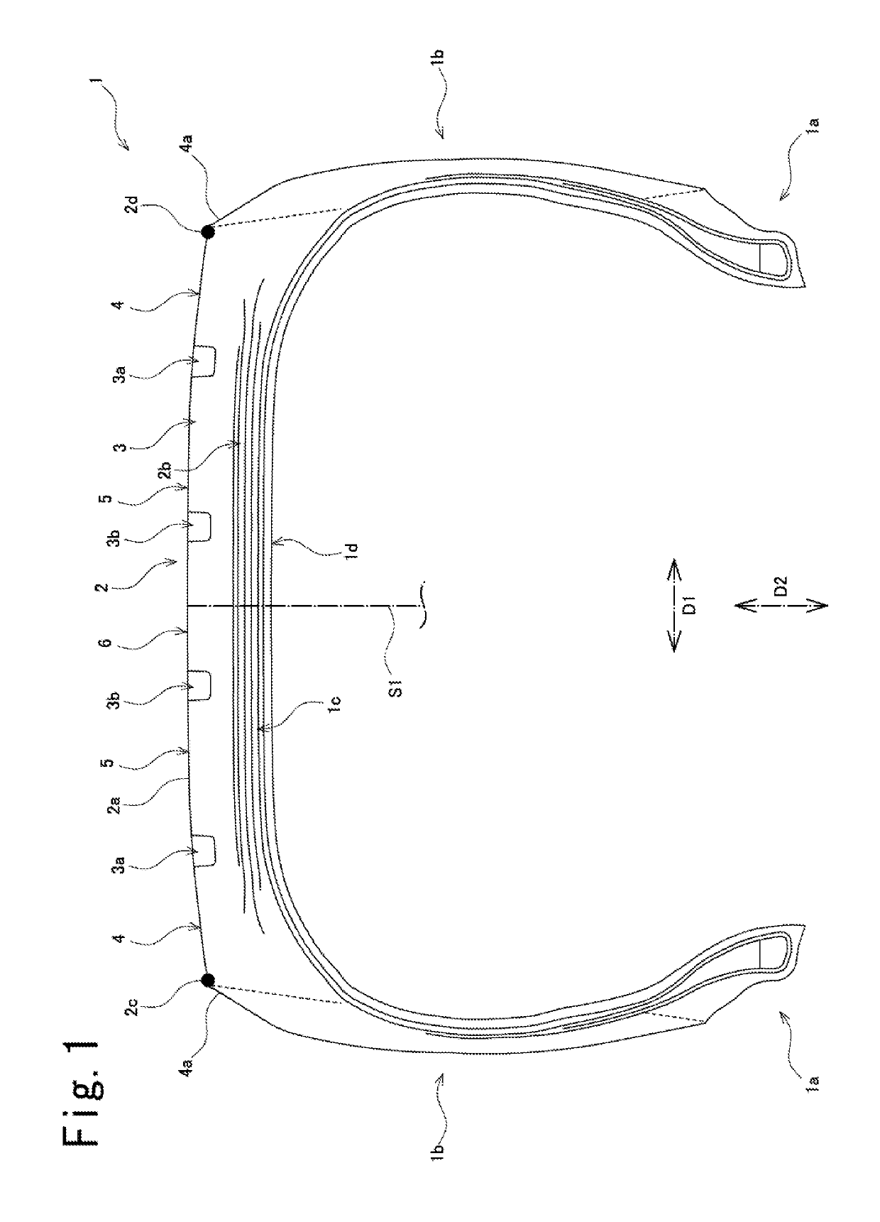
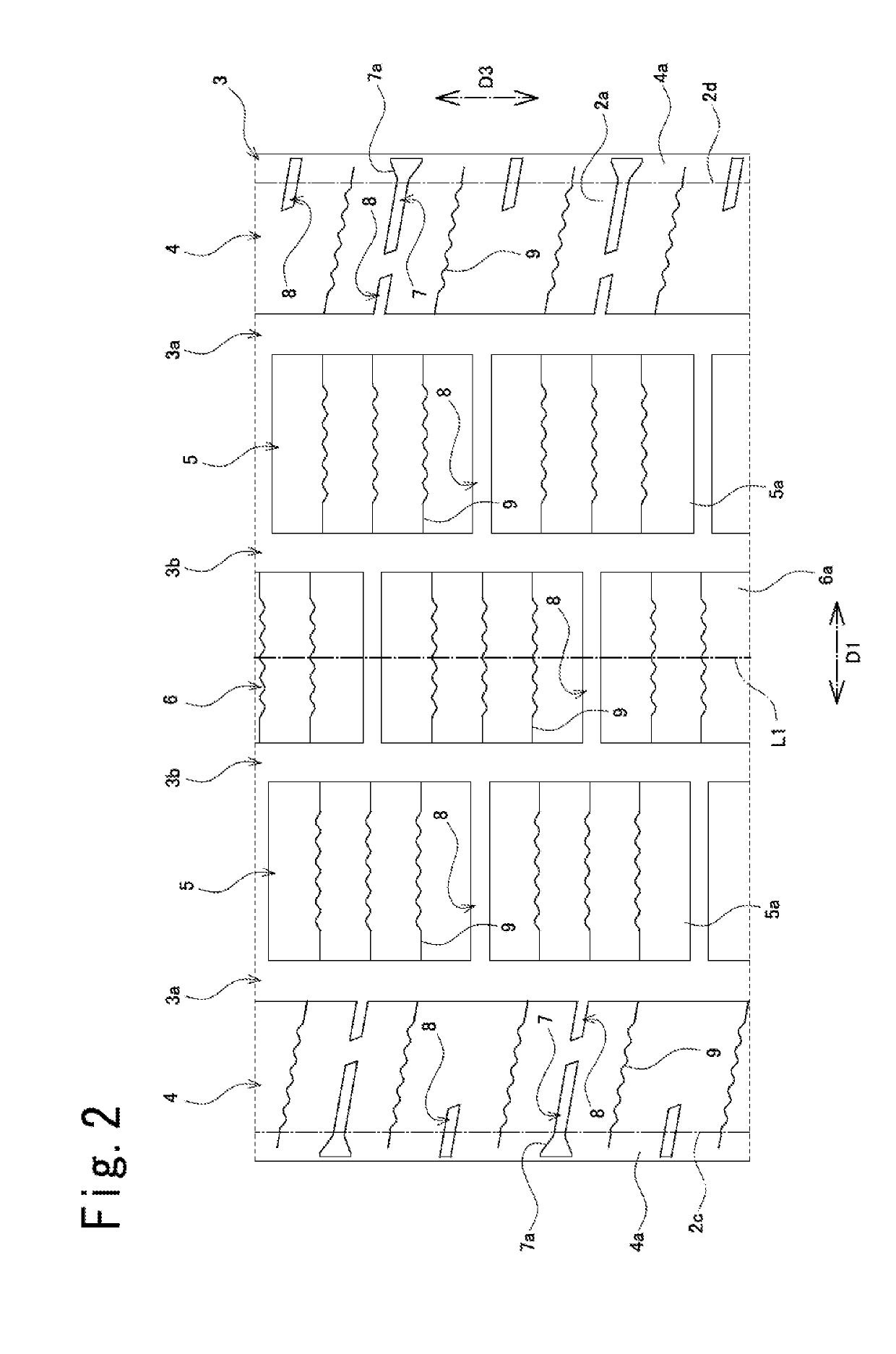
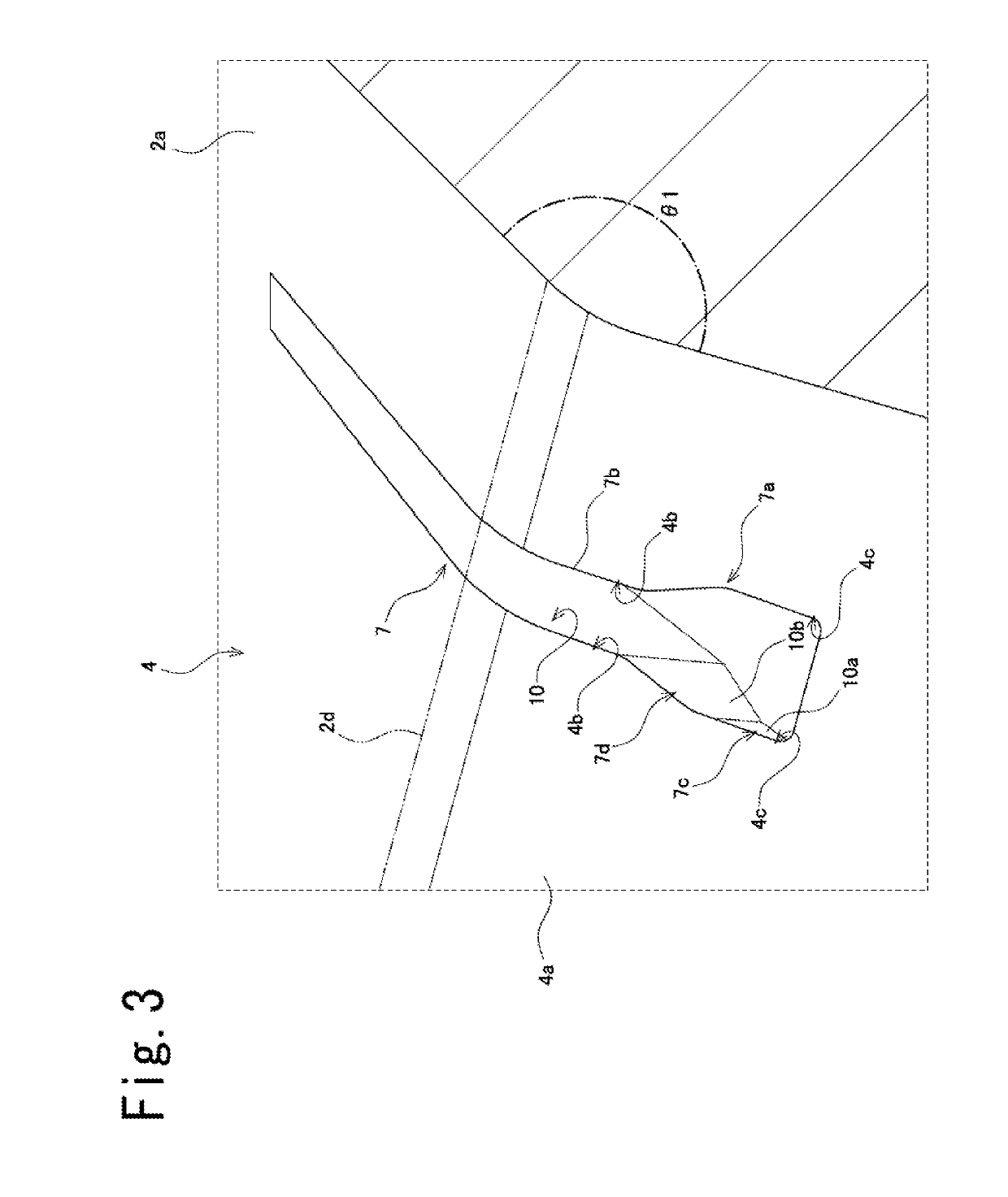
[0034]Below, an embodiment of a pneumatic tire is described with reference to FIG. 1 through FIG. 5. At the respective drawings, note that dimensional ratios at the drawings and actual dimensional ratios are not necessarily consistent, and note further that dimensional ratios are not necessarily consistent from drawing to drawing.

[0035]At the respective drawings, first direction D1 is the tire width direction D1 which is parallel to the tire rotational axis which is the center of rotation of pneumatic tire (hereinafter also referred to as simply “tire”) 1, second direction D2 is the tire radial direction D2 which is the direction of the diameter of tire 1, and third direction D3 is the tire circumferential direction D3 which is circumferential with respect to the rotational axis of the tire.

[0036]Tire equatorial plane S1 refers to a plane that is located centrally in the tire width direction D1 of tire 1 and that is perpendicular to the rotational axis of the tire; tire meridional p...


PUM


Abstract

A pneumatic tire includes a plurality extending in a tire circumferential direction, and a plurality of land portions that are partitioned by the plurality of main grooves; the plurality of land portions include at least one shoulder land portion arranged in outwardmost fashion in a tire width direction; the at least one shoulder land portion comprises a plurality of width grooves of groove width of less than 2 mm; and at least one of the plurality of width grooves extends as far as a outside end in the tire width direction of the at least one shoulder land portion and comprises, at a location toward the exterior the tire width direction from a contact patch end, a wide portion at which groove width increases toward a groove bottom.

Description

CROSS REFERENCE TO RELATED APPLICATIONS[0001]This application claims the benefit of priority of Japanese application no. 2017-249621, filed on Dec. 26, 2017, which is incorporated herein by reference.BACKGROUND OF THE INVENTIONField of the Invention[0002]The present invention relates to a pneumatic tire.Description of the Related Art[0003]Conventionally a pneumatic tire might, for example, comprise a plurality of main grooves extending in the tire circumferential direction, and a plurality of land portions which are partitioned by the main grooves (e.g., JP 2009-190665 A). In addition, shoulder land portion(s) arranged in outwardmost fashion in the tire width direction might comprise width groove(s) extending as far as outside end(s) in the tire width direction.[0004]With pneumatic tires, it so happens that water shedding performance tends to decrease due to the lowering of the void fraction within the region of the contact patch that occurs in accompaniment to wear. On the other ha...

Claims


Application Information

Patent Timeline
Patent Type & Authority Applications(United States)
IPC IPC(8): B60C11/03B60C11/01B60C11/12
CPCB60C11/0309B60C11/01B60C2011/1213B60C2011/0358B60C11/1204B60C2011/0341B60C2011/013B60C11/1369B60C2011/039B60C2011/0381B60C2011/0365B60C11/0306
Inventor KUWANO, SHINGO
Owner TOYO TIRE & RUBBER CO LTD
Why Eureka
Try Eureka