

Pneumatic tire
a technology of pneumatic tires and sacrificial lugs, which is applied in the direction of vehicle components, transportation and packaging, non-skid devices, etc., can solve the problems of sacrificial lugs breaking off and cracking at the bottom of the defense groove, and achieve the effect of preventing damag
Inactive Publication Date: 2018-06-21
TOYO TIRE & RUBBER CO LTD
View PDF3 Cites 0 Cited by
- Summary
- Abstract
- Description
- Claims
- Application Information
AI Technical Summary
Benefits of technology
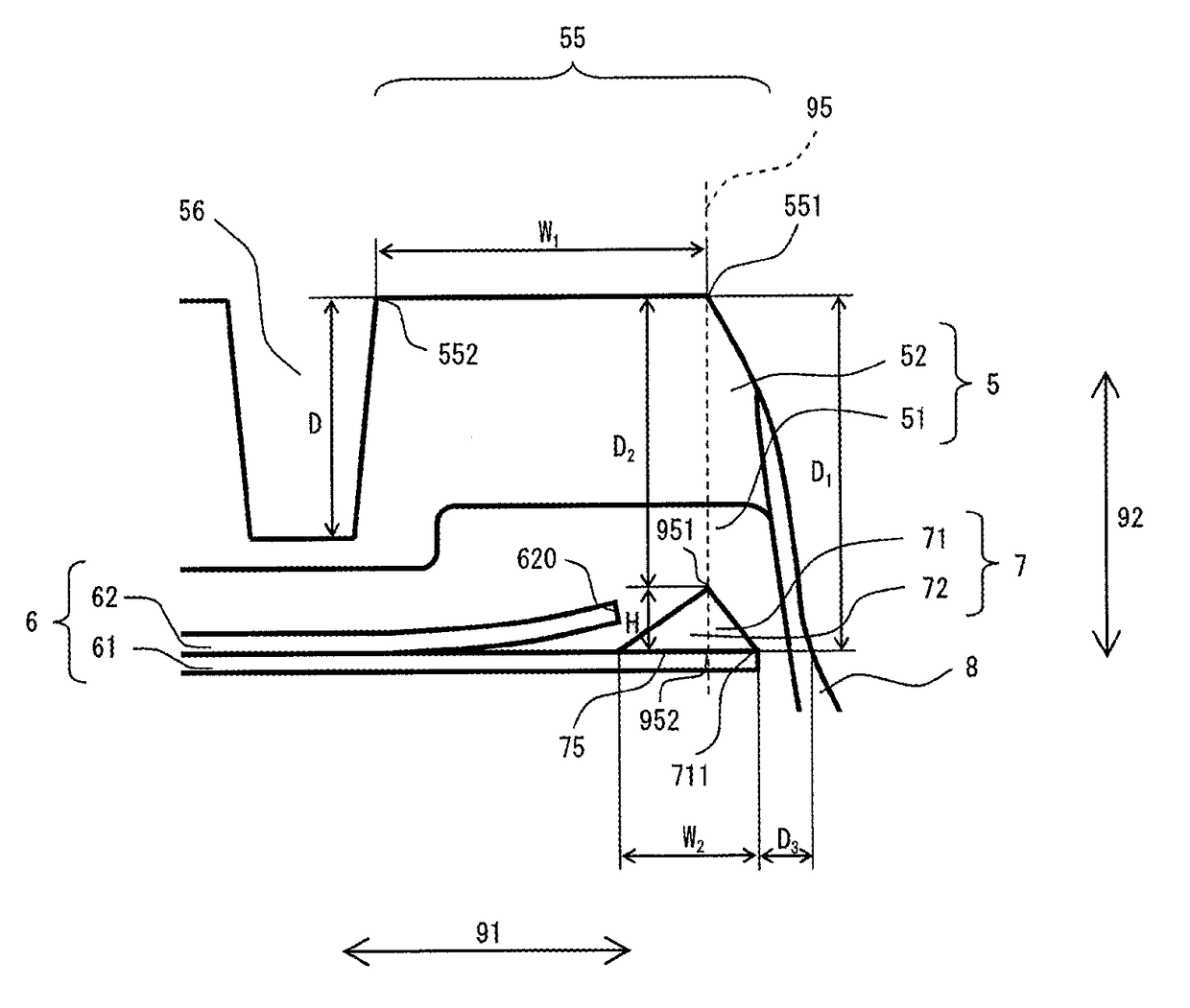
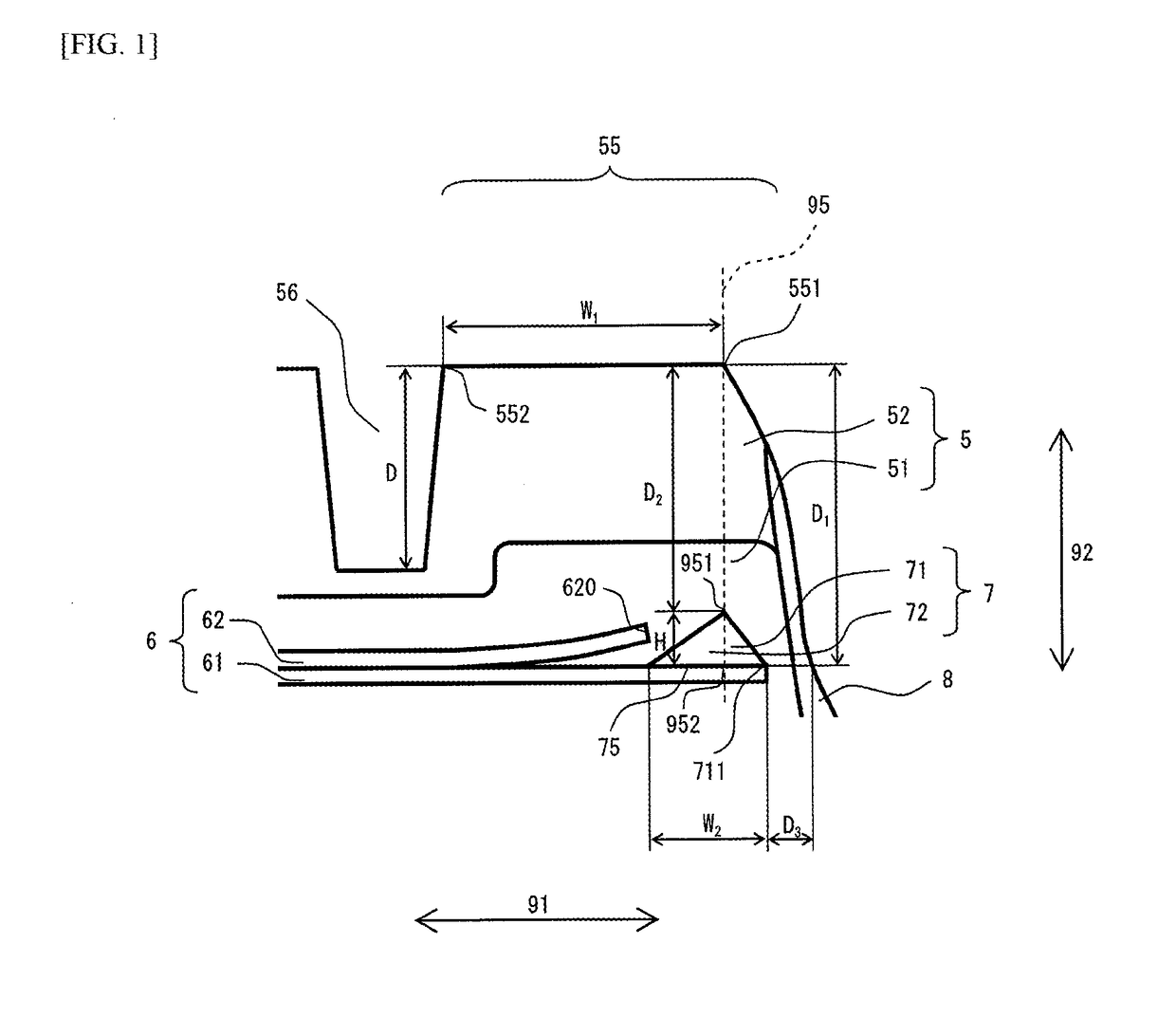
The present invention aims to reduce contact patch pressure at the shoulder lug and improve resistance to uneven wear without using a defense groove. A contact patch pressure reducing rubber region is created between the belt and base rubber layer to achieve this. The rubber region has a first face that comes in contact with the belt and a distance between the tread surface at the shoulder lug and the first face is set to prevent exposure of the rubber region due to abrasion of the tread rubber. Additionally, the invention includes setting a distance between the side face of the tire and the end of the rubber region to prevent damage to the rubber region in case of tire damage. These measures allow for proper functioning of the contact patch pressure reducing rubber region and improved performance of the tire.
Problems solved by technology
However, where defense grooves are provided, there is a possibility that cracking will occur at the bottom of the defense groove and there is a possibility that the sacrificial lug portion will break off therefrom.
Method used
View moreImage
Smart ImageViewing Examples

Examples
working examples
[0036]Working examples and the like which illustrate the constitution and effect of the present invention in specific terms are described below.
working examples 1-3
[0037]A test tire having the configuration shown in FIG. I was fabricated. Width W1 was 40 mm. Details are shown in TABLE 1.
Login to View More PUM
 Abstract
A pneumatic tire includes a tread rubber region 5 a belt region 6 including a belt 61 and a contact patch pressure reducing rubber region 7, wherein tread rubber region 5 includes base rubber layer 51 and cap rubber layer 52. The two ends of the tread surface at shoulder lug 55 have first end 551 and a second end (not shown) which is located toward an interior in a tire width direction from first end 551. A contact patch pressure reducing rubber region 7 is disposed at a location between belt 61 and base nibber layer 51. The modulus of contact patch pressure reducing rubber region 7 is lower than the modulus of base rubber layer 51 and is lower than the modulus of cap rubber layer 52.
Description
TECHNICAL FIELD[0001]The present disclosure relates to a pneumatic tire.BACKGROUND ART[0002]At a running pneumatic tire, contact patch pressure at shoulder lugs on the tread surface in the vicinity of the edge of the contact patch being high, the amount of wear at shoulder lugs in the vicinity of the edge of the contact patch is ordinarily greater than at lugs elsewhere on the tread surface.[0003]To prevent such uneven wear, shoulder lugs are sometimes provided with defense grooves. The defense grooves cause shoulder lugs to be divided into main lug portions toward the interior in the tire width direction from the defense groove, and sacrificial lug portions toward the exterior in the tire width direction from the defense groove, as a result of which wear of the main lug portions is suppressed.[0004]However, where defense grooves are provided, there is a possibility that cracking will occur at the bottom of the defense groove and there is a possibility that the sacrificial lug porti...
Claims
Login to View More Application Information
Patent Timeline
 IPC IPC(8): B60C27/02B60C11/03B60C11/00
CPCB60C27/0207B60C11/0311B60C11/005B60C2011/0313B60C2009/1871B60C11/0008B60C2011/0025B60C2011/0016B60C2009/1842B60C9/1835B60C9/185B60C11/01
InventorHASEDA, HIROYUKI
OwnerTOYO TIRE & RUBBER CO LTD