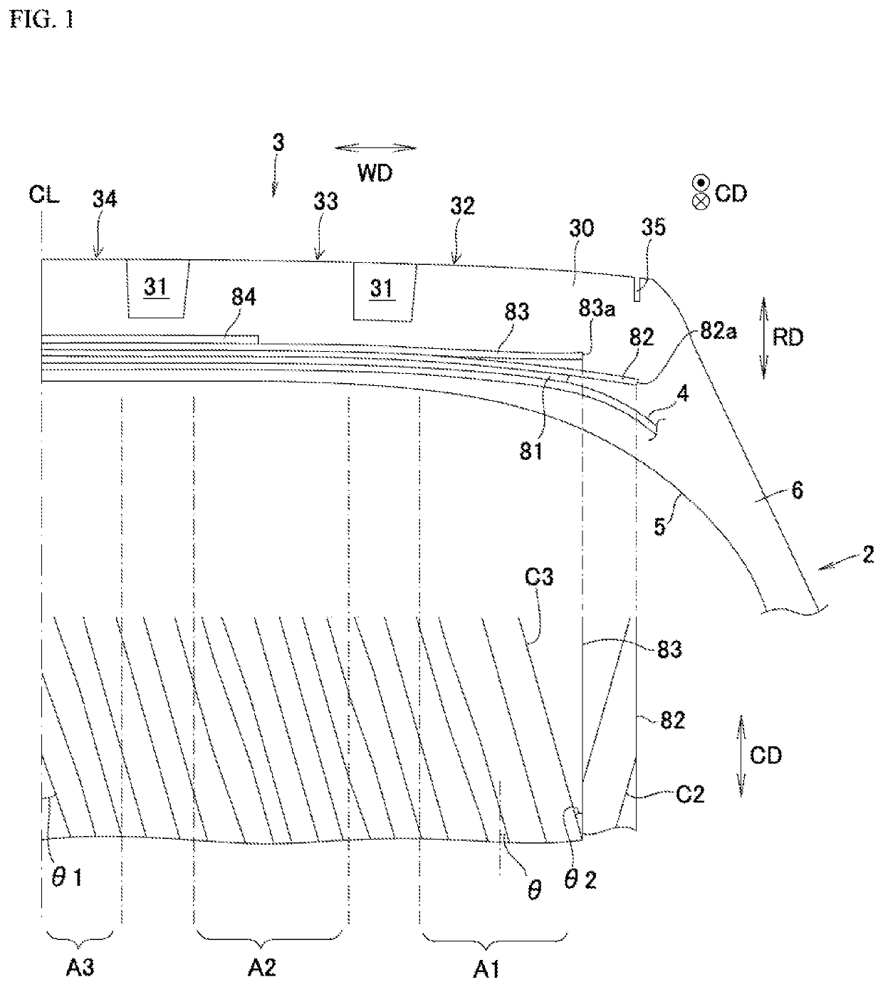
Pneumatic tire

a technology of pneumatic tires and pneumatic cylinders, applied in the field of pneumatic tires, can solve problems such as inability to achieve the desired effect, and achieve the effect of suppressing the radial increase in dimensions and improving the resistance to uneven wear

Active Publication Date: 2021-10-12
TOYO TIRE & RUBBER CO LTD
View PDF3 Cites 0 Cited by
  • Summary
  • Abstract
  • Description
  • Claims
  • Application Information

AI Technical Summary

Benefits of technology

[0006]The present disclosure was conceived in view of such issues, it being an object thereof to provide a pneumatic tire possessing improved resistance to uneven wear and suppression of radial increase in dimensions at shoulder regions during driving.
[0013]As a result of adoption of such a constitution, it will be possible to improve resistance to uneven wear and to suppress increase in radial dimensions at shoulder regions during driving.

Problems solved by technology

However, as a major groove angle of 30° to 45° is impractical, being too large, the inventor(s) were unable to achieve the desired benefit despite their best efforts.

Method used


Image

  • Pneumatic tire
  • Pneumatic tire
  • Pneumatic tire

Examples


working examples

[0049]To illustrate the constitution and effect of the present disclosure in specific terms, evaluation was carried out as follows with respect to the following working examples.

[0050](1) Radial Increase in Dimensions During Driving

[0051]Under conditions such that tire size was 295 / 75R22.5, rim size was 22.5×8.25, and air pressure was 760 kPa, inside diameter was measured for three situations—these being the tire as mounted on its rim but before being fully inflated, the tire as fully inflated but before being placed in service, and the tire as fully inflated following increase in dimensions during driving—and the amount of change in the inner surface between the tire as mounted on its rim but before being fully inflated and the tire as fully inflated following increase in dimensions during driving was expressed in terms of an index. Results are shown as indexed relative to a value of 100 for Comparative Example 1, the smaller the index the less the increase in radial dimensions dur...
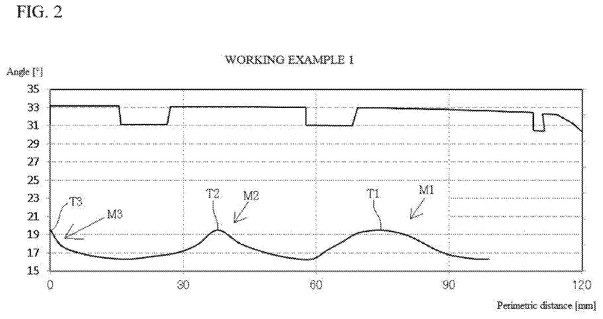
working example 1

[0054]Angle of inclination of cords C3 at third belt ply 83 was made to be as shown in FIG. 2. Second belt ply 82 was flipped relative to third belt ply 83. This was made to be such that angle θ1 of inclination at tire equator CL>angle θ2 of inclination at belt end 83a. This was made to be such that θ1=19.5° and θ2=16.3°. A first mounded region M1 in which angle varied and which corresponded to shoulder rib 32 was provided; a second mounded region M2 in which angle varied and which corresponded to mediate rib 33 was provided; and a third mounded region M3 in which angle varied and which corresponded to center rib 34 was provided. Angles θ of inclination at peaks T1, T2, and T3 at the respective mounded regions M1, M2, and M3 in which angle varied were all the same, being 19.5°.
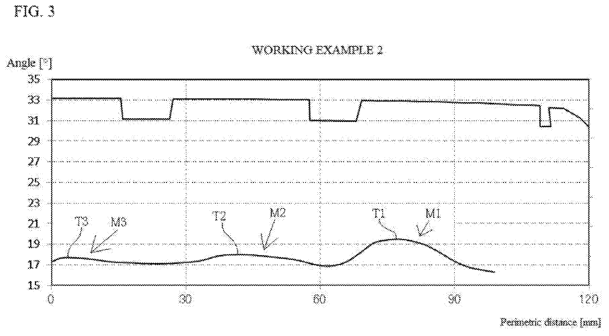
working example 2

[0055]Angle of inclination of cords C3 at third belt ply 83 was made to be as shown in FIG. 3. This was made to be such that angle θ1 of inclination at tire equator CL>angle θ2 of inclination at belt end 83a, this being made such that θ1=17.3° and θ2=16.3°. Angles θ of inclination at peaks T1, T2, and T3 of first mounded region M1 in which angle varied, second mounded region M2 in which angle varied, and third mounded region M3 in which angle varied increased in magnitude as one proceeds from a location toward the tire equator to a location toward the exterior in the tire width direction. Angle θ of inclination at peak T3 of third mounded region M3 in which angle varied was 17.7°, angle θ of inclination at peak T2 of second mounded region M2 in which angle varied was 18°, and angle θ of inclination at peak T1 of first mounded region M1 in which angle varied was 19.5°. In other respects, it was similar to Working Example 1.


PUM

PropertyMeasurementUnit
angle of inclinationaaaaaaaaaa
anglesaaaaaaaaaa
groove angleaaaaaaaaaa

Abstract

A tire having four belt plies laminated at an outside circumference of the carcass. Cords at second and third belt plies among the four belt plies, as numbered from the carcass to the outside circumference, intersect, being inclined in mutually opposite fashion with respect to a tire axis. Angles of inclination with respect to the tire circumferential direction of the second and third belt plies are such that an angle at a belt end is less than an angle at a tire equator. A first mounded region that has a peak at which the angle of inclination is greater than at a periphery and that corresponds to a shoulder rib which among the plurality of ribs is provided. The peak at the first mounded region is arranged at a shoulder rib region which appears to overlap the shoulder rib as seen in plan view.

Description

BACKGROUND OF THE INVENTIONField of the Invention[0001]The present disclosure relates to a pneumatic tire intended for heavy loads in which a rib extending in the tire circumferential direction is formed at the tread.Description of the Related Art[0002]A pneumatic tire intended for heavy loads which may be employed in trucks, buses, and so forth is a radial tire that has a carcass having steel cord(s) arranged so as to emanate in radial fashion from a central location at the axis of the tire. Four belt plies having steel cords are laminated at the outside circumference of the carcass. Major grooves which extend in the tire circumferential direction are formed at the tread, and ribs which are partitioned by major grooves extend in the tire circumferential direction. A pneumatic tire intended for heavy loads and referred to as a rib tire is a tire in which only ribs are formed at the tread.[0003]A tire intended for heavy loads is disclosed at Japanese Patent Application Publication Ko...

Claims


Application Information

Patent Timeline
Patent Type & Authority Patents(United States)
IPC IPC(8): B60C9/18B60C9/20B60C9/22B60C11/00B60C9/00B60C11/04B60C11/03
CPCB60C9/2006B60C9/0007B60C9/22B60C11/0083B60C11/04B60C2009/2016B60C2009/2025B60C2009/2074B60C2011/0386B60C2011/0388B60C2200/06
Inventor SUITA, HARUNOBU
Owner TOYO TIRE & RUBBER CO LTD
Why Eureka
Try Eureka