
Device and method for joining a lens to a housing of a lighting device of a motor vehicle
a technology for motor vehicles and housings, applied in the direction of manufacturing tools, transportation and packaging, lighting and heating apparatus, etc., can solve the problems of high cost, manufacturing process, and only account for dimensional deviations in functional dimensions
- Summary
- Abstract
- Description
- Claims
- Application Information
AI Technical Summary
Benefits of technology
Problems solved by technology
Method used
Image

Examples
Embodiment Construction
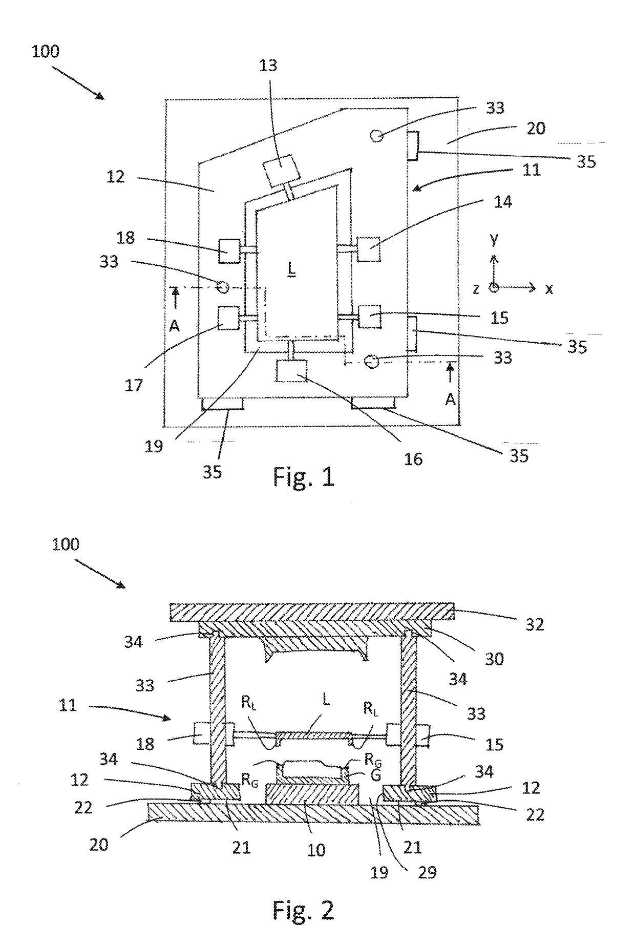
[0022]Shown schematically in FIGS. 1 and 2 is a device 100 for installing a lens L on a housing G of a lighting device of a motor vehicle. The lens L is attached to the housing G by means of a joining process, in particular a welding process, in that the edge region RL of the lens L is integrally connected to the edge region RG of the housing G. Prior to the joining, the lens L and housing G must be aligned with one another in order to compensate for tolerance deviations.
[0023]The device 100 has a receptacle device 10, as can be seen in FIG. 2, to accommodate the housing G. In the receptacle device 10, the housing G can be aligned on a reference point system by placing the housing G on this reference point system. The reference point system can have multiple reference points spaced apart from one another, which are spread out or positioned in an x-y plane. A defined positioning of the housing G in the receptacle device 10, and thus in the device 100, can be accomplished by means of ...
PUM
| Property | Measurement | Unit |
|---|---|---|
| displacement | aaaaa | aaaaa |
| welding forces | aaaaa | aaaaa |
| distances | aaaaa | aaaaa |
Abstract
Description
Claims
Application Information