Bearing Arrangement

a bearing and arrangement technology, applied in the field of bearing arrangement, can solve the problems of unable to perform maintenance or optionally replace the seal later without having to remove the entire bearing, and the prior-art plain bearing is inevitably asymmetric, and achieves the effects of reducing production, assembly and maintenance costs, avoiding asymmetrical, and ensuring the integrity of the bearing

Inactive Publication Date: 2008-12-25
ZF FRIEDRICHSHAFEN AG
View PDF17 Cites 6 Cited by
  • Summary
  • Abstract
  • Description
  • Claims
  • Application Information

AI Technical Summary

Benefits of technology

[0008]Against this background, the object of the present invention is to create a bearing arrangement, which overcomes the drawbacks of the state of the art. In particular, the need to split the bearing arrangement into two parts and the problems associated therewith in terms of axial clearance shall be eliminated. Furthermore, the construction of the bearing arrangement shall make possible modular manufacture as well as assembly and lower production, assembly and maintenance costs associated therewith. Finally, the bearing arrangement shall have the smallest possible tolerances, excellent tightness, high axial rigidity and optionally also radial rigidity as well as high loadability and service life.

Problems solved by technology

However, this prior-art plain bearing is, on the one hand, inevitably asymmetrical or in the form of two halves and it must therefore be installed, in general, in an arrangement that is mirror-inverted in pairs.
In addition, the one-piece design of the seal with the rubber body surrounding the bearing makes difficult, on the one hand, the deformation-free mounting especially of the seal and makes it, moreover, impossible to perform maintenance or optionally to replace the seal later without having to remove the entire bearing.
Finally, this prior-art plain bearing has, due to its construction, both a high axial elasticity as well as a high radial elasticity, which is, however, undesirable for certain applications of plain bearings.
The sealing against environmental effects also often fails to meet high requirements in such prior-art bearing arrangements.

Method used


Image

  • Bearing Arrangement
  • Bearing Arrangement
  • Bearing Arrangement

Examples


Embodiment Construction

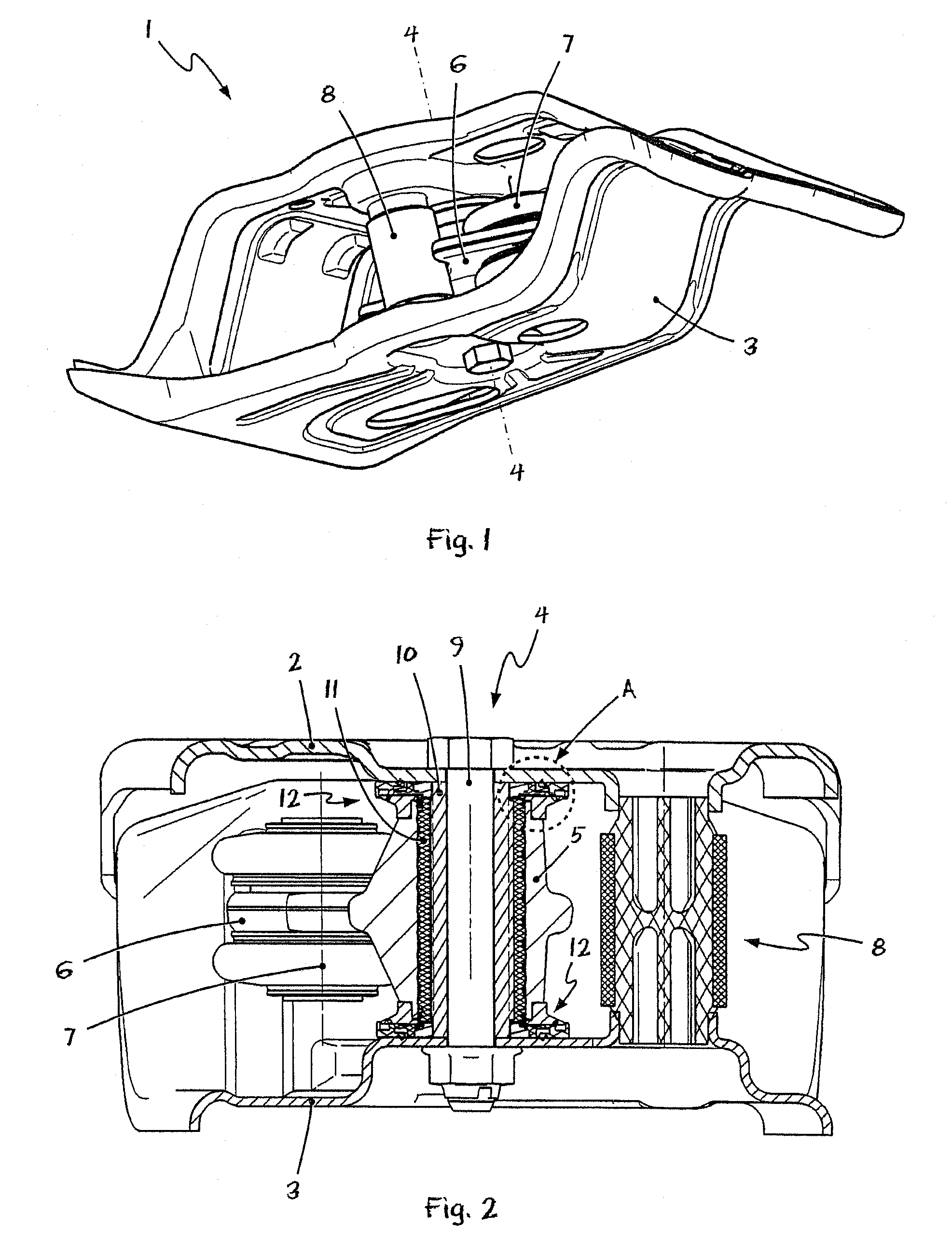
[0040]Referring to the drawings in particular, FIG. 1 shows first the assembly of a central joint 1 for a Watt's linkage of a motor vehicle axle in a schematic view.

[0041]Two sheet metal components 2, 3, which form the housing and the bearing block of the central joint 1, respectively, are recognized at first. The rocker or coupler 6 of the Watt's linkage, which is visible in FIG. 1 only partially, is connected to a rotatable outer bush 5 of a bearing arrangement 4, which is located behind the coupler 6 in the view according to FIG. 1 sand is therefore hidden. The two sleeve joints 7 of the coupler 6, of which only a sleeve joint 7 is visible partially in FIG. 1, are used to articulate and kinematically couple the pushing struts of the Watt's linkage (which are not shown here).

[0042]It becomes recognizable from FIG. 1 that the central joint 1 has an extremely compact and hence space-saving and lightweight design, which does, however, lead to even stronger forces and torques in the a...


PUM


Abstract

A bearing arrangement (4) is provided with a bearing inner bush (10) and an outer bush (5), especially for the central joint (1) of a Watt's linkage. The bearing arrangement (4) is provided with a sealing arrangement (12) surrounding the front-side bearing gap between the inner bush (10) and the outer bush (5). The sealing arrangement (12) comprises an elastic sealing element (14) with static as well as dynamic sealing surfaces. The bearing arrangement (4) has a sealing arrangement (12) designed as a sealing module (12), which can be connected to the bearing inner bush (10), the sealing module (12) also comprising a running surface (15) for the axial bearing of the outer bush (5). The arrangement makes possible the especially economical production of modularly designed, highly loadable bush bearings. Furthermore, undivided, continuous bearing bushes can be used, which improves the ability to be mounted and the precision and the service life of the bearing arrangement. It is also possible, especially in case of highly stressed bush bearings, to dimension the axial rigidity as well as the radial rigidity of the bearing arrangement independently from one another, and especially good sealing is obtained against environmental effects.

Description

CROSS REFERENCE TO RELATED APPLICATIONS[0001]This application is a United States National Phase application of International Application PCT / DE2005 / 001238 and claims the benefit of priority under 35 U.S.C. § 119 of German Patent Application DE 10 2004 035 073.6 filed Jul. 20, 2004, the entire contents of which are incorporated herein by reference.FIELD OF THE INVENTION[0002]The present invention pertains to a bearing arrangement, especially for the central joint of a Watt's linkage.BACKGROUND OF THE INVENTION[0003]Bearing arrangements of this class are used, for example, but by no means exclusively, as central joints in Watt's linkages. Watt's linkages are used especially in rear axles of high-quality motor vehicles. The Watt's linkage connects the wheel suspensions of the two rear wheels to one another as well as to the chassis and the vehicle body such that spring compression of one or both rear wheels is possible without hindrance, whereas lateral motions of the rear axle or the ...

Claims


Application Information

Patent Timeline
Patent Type & Authority Applications(United States)
IPC IPC(8): F16C33/74
CPCB60G7/02B60G2200/342B60G2204/418B60G2204/421B60G2204/4302B60G2204/4402F16C33/74F16C17/10F16C27/06
Inventor BLANKE, ARNOLDMAEHLMANN, DIRKROESLER, THOMASSCHMIDT, UWE
Owner ZF FRIEDRICHSHAFEN AG
Why Eureka
Try Eureka