Panel with a slider

Active Publication Date: 2016-01-14
VÄLINGE INNOVATION AB
View PDF2 Cites 46 Cited by
  • Summary
  • Abstract
  • Description
  • Claims
  • Application Information

AI Technical Summary

Benefits of technology

[0005]It is an object of certain embodiments of the present disclosure to provide an improvement over the above described techniques and kn

Problems solved by technology

A drawback with the known systems is that it time consuming to assemble the sliders to the furniture.
When the drawer with a load is pulled out

Method used


Image

  • Panel with a slider
  • Panel with a slider
  • Panel with a slider

Examples


Example

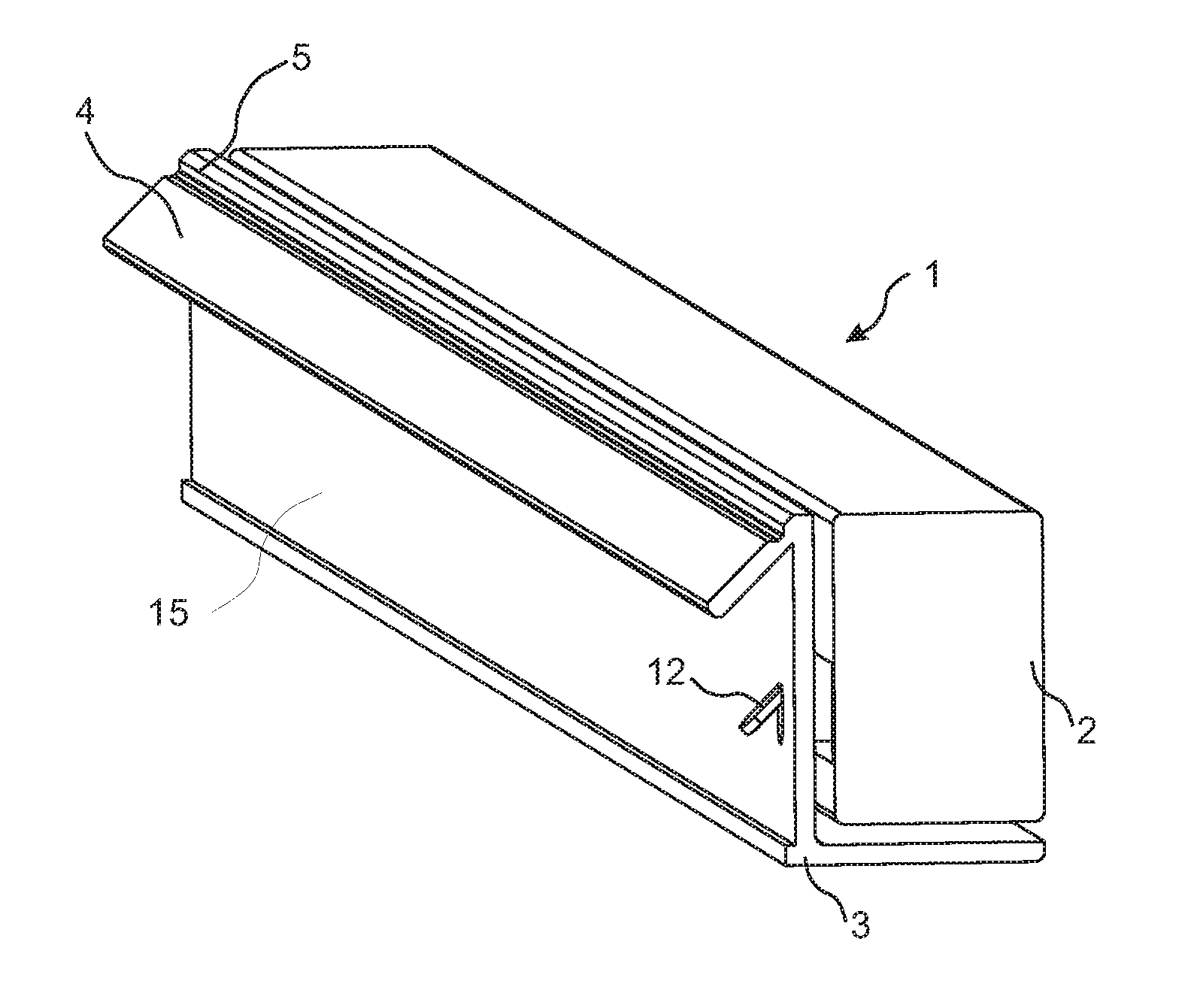
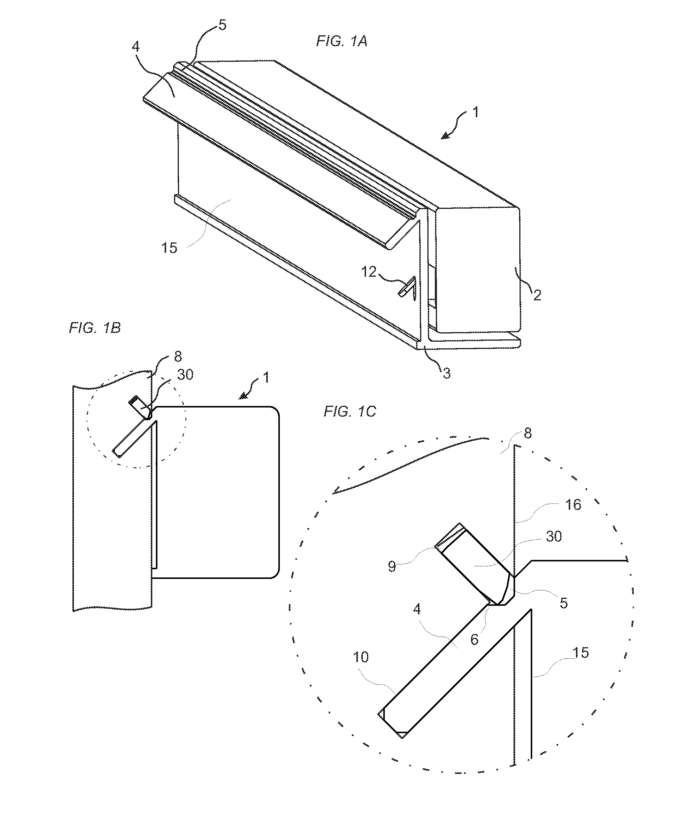
[0031]An embodiment of the disclosure is shown in FIG. 1A-C. FIG. 1C shows an enlargement of the encircled area of FIG. 1B, which shows a schematic drawing of a panel 8 and a slider 1. The embodiments include a set, which may be a part of a furniture or kitchen furnishing, comprising a panel 8 and a slider 1, such as a drawer slider. The panel may be of a rectangular shape and arranged such that it extends in a vertical direction. The slider may comprise an inner part 3, which is assembled to the panel, and an outer part 2, which is configure to be connected to a drawer (not shown in the figures). The outer part may be displaceable relative the inner part. The slider comprises a first surface 15 and the panel comprising a second surface 16. The slider is configured to be assembled to the panel with the first surface 15 facing the second surface 16. The second surface 16 is provided with an insertion groove 10 and a displacement groove 9, which are of a longitudinal shape extending a...


PUM


Abstract

A panel provided with a slider. The slider including a first surface and the panel including a second surface, the slider is being configured to be assembled to the panel with the first surface facing the second surface. The second surface is provided with an insertion groove and a displacement groove, which are of a longitudinal shape. A first angle, which is between the second surface and the insertion groove, is an acute angle. A strip protrudes from the first surface. A second angle, which is between the strip and the first surface, is an acute angle. The strip is configured to be inserted into the insertion groove when the slider is assembled to the panel. A displaceable tongue is arranged in the displacement groove. A locking surface of the displaceable tongue is configured to cooperate with a locking surface of the strip for locking the strip to the panel.

Description

CROSS REFERENCE TO RELATED APPLICATIONS[0001]The present application claims the benefit of Swedish Application No. 1450891-5, filed on Jul. 11, 2014. The entire contents of Swedish Application No. 1450891-5 are hereby incorporated herein by reference in their entirety.TECHNICAL FIELD[0002]The present disclosure relates to a fastening device for connecting a runner, such as a drawer runner to a panel, such as a building panel, a wall panel, furniture component or the like.TECHNICAL BACKGROUND[0003]Drawer sliders are known that are fixed to, e.g., furniture by screws. A drawback with the known systems is that it time consuming to assemble the sliders to the furniture.[0004]The above description of various known aspects is the applicant's characterization of such, and is not an admission that any of the above description is considered as prior art.SUMMARY[0005]It is an object of certain embodiments of the present disclosure to provide an improvement over the above described techniques ...

Claims


Application Information

Patent Timeline
IPC IPC(8): A47B88/12A47B88/16F16B5/12F16B12/10
CPCA47B88/16F16B5/126F16B12/10A47B88/12A47B88/931A47B88/938A47B88/43A47B2088/4235A47B88/402
Inventor DERELOV, PETER
Owner VÄLINGE INNOVATION AB
Why Eureka
Try Eureka