Method and system of transitive matching for object recognition, in particular for biometric searches
Inactive Publication Date: 2005-07-19
MORPHOTRUST USA
0 Cites 47 Cited by
AI-Extracted Technical Summary
Problems solved by technology
Because human faces and other biometric identifiers may display significant variation in appearance due, for instance, to changes in facial expression, orientation, facial hair, or lighting conditions, it is often difficult for face recognition systems to identify faces which exhibit considerable variation in appearance.
Although the accuracy of these and other re...
View moreMethod used
[0029]FIG. 1 is a block diagram illustrating how a transitive recognition system 100 of the present invention may be used with an underlying object or biometric recognition system 150 to improve the speed and efficiency of recognition matching. Conceptually, transitive recognition system 100 preferably includes four main software modules: a sample space construction and score rotation module 110, a sample space truncation and measure module 120, a recognition space construction and score rotation module 130, and a recognition space truncation and measure module 140. During operation, these modules use certain object or biometric sample databases 170, as shown in FIG. 1 and described in detail below. System 100 of the present invention exploits the transitive property described above to provide much faster and more efficient recognition and matching than that available with the underlying recognition system and algorithm 150 alone. In effect, the underlying recognition algorithm 150 generates “raw” scores that act as inputs to transitive system 100. The underlying or raw recognition system 150 may use any suitable recognition algorithm for generating raw matching scores and may be based, for example, on eigenface, dynamic link matching, probabilistic matching, or support vector techniques as referenced above. For example, recognition system 150 may capture sample biometric data from an individual 160 generate a raw score based on that sample data.
[0030]The transitive property is illustrated conceptually in FIGS. 2A and 2B. Referring to FIG. 2A, instead of directly comparing the biometric data of sample A with the biometric data of sample C, the data of samples A and C are independently compared with a third basis or reference sample B. By virtue of the transitive property, if sample A has a high score S(A) against sample B and sample C also has a high score S(C) against sample B, then there is a high likelihood (i.e. there is an increased probability) that sample A has a high score against sample C. In the present invention, the transitive property is applied to an underlying match algorithm using a plurality of basis sample elements, shown as B1 to BNB in FIG. 2B (and contained in database DBB in FIG. 1). As described in detail below, recognition may be much more rapidly established by comparing the scores S(A) of sample A with each basis element B1 to BNB to the scores S(C) of sample C with the same basis elements, as fundamentally illustrated in FIG. 2B. In this manner, the score vectors S(A) and S(C) each provide encoded recognition information that may be used to measure nearness in a biometric vector space created by the basis elements B1 to BNB. Different recognition measures for determining the similarity or nearness of the score vector S(A)={S1(A), S2(A), . . . SNB(A)}T and the score vector S(C)={S1(C), S2(C), . . . SNB(C)}T can be used. For example, M(A,C)=1NB∑NB [SI(A)-SI(C)]2
[0031]However, because the set of basis elements is a finite set, a transitive recognition measure—such as M(A,C)—that determines the similarity between the scopes S(A) and S(C) does not produce optimal results for the classification or recognition of biometrics. In accordance with the present invention, transitive recognition system 100 performs a first sample space rotation, and preferably also second recognition space rotatio...
View moreBenefits of technology
[0008]The present invention provides a method and system of transitivity matching suitable for object recognition, and in particular biometric recognition such as face or fingerprint recognition. The invention provides a highly efficient means for pre-encoding object match information from each set of raw object sample data, such as a face image or a fingerprint, to be stored in a database or to be checked against a database. With the transitive recognition method and system of the present invention, the time required for the recognition system to perform matching is dramatically reduced compared to that of an und...
View moreAbstract
A method and system of transitivity matching suitable for object recognition, and in particular biometric recognition such as face or fingerprint recognition, is provided. The invention provides a means for pre-encoding object match information from each set of raw object sample data or scores from an underlying recognition algorithm. A sample space is constructed and the raw scores are mapped into that space. Preferably, a recognition space is also constructed and the same space scores are further mapped into the recognition space. Each space may be truncated to remove dispensable modes of that space. The distance between object data samples encoded in the sample space or the recognition space can be more rapidly determined, and the encoded data samples are also significantly compressed, compared to the raw scores.
Application Domain
Technology Topic
Image
Examples
- Experimental program(1)
Example
[0027]Although the description which follows relates primarily to biometric recognition techniques such as face or fingerprint recognition, it will be appreciated that the transitive recognition method and system of the present invention may be generally extended to recognition of other types of objects or patterns.
[0028]In biometric recognition, the comparison of the data for a number of biometric identifiers does not return a Boolean (true/false) matching score when one data sample set is compared against another. Instead, the recognition algorithm returns an overlap or distance score, S, based on the notion of nearness or similarity. This is the case for face and fingerprint recognition systems, but is also commonplace in other types of object and pattern recognition systems. Since biometric scores obey a transitive property, described below, a score comparing the biometrics of different individuals may containing relevant and meaningful match information even through the individuals do not represent a match.
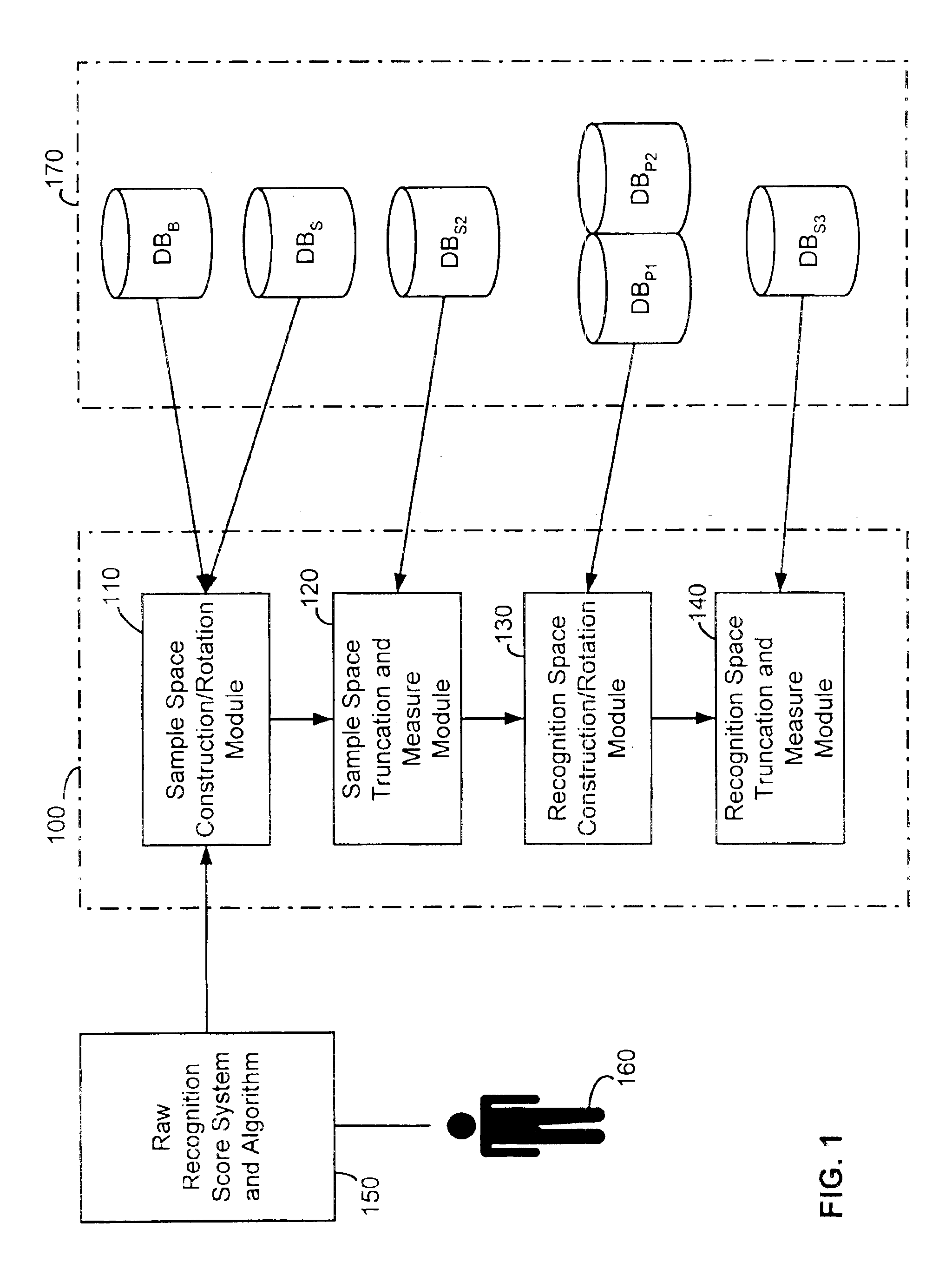
[0029]FIG. 1 is a block diagram illustrating how a transitive recognition system 100 of the present invention may be used with an underlying object or biometric recognition system 150 to improve the speed and efficiency of recognition matching. Conceptually, transitive recognition system 100 preferably includes four main software modules: a sample space construction and score rotation module 110, a sample space truncation and measure module 120, a recognition space construction and score rotation module 130, and a recognition space truncation and measure module 140. During operation, these modules use certain object or biometric sample databases 170, as shown in FIG. 1 and described in detail below. System 100 of the present invention exploits the transitive property described above to provide much faster and more efficient recognition and matching than that available with the underlying recognition system and algorithm 150 alone. In effect, the underlying recognition algorithm 150 generates “raw” scores that act as inputs to transitive system 100. The underlying or raw recognition system 150 may use any suitable recognition algorithm for generating raw matching scores and may be based, for example, on eigenface, dynamic link matching, probabilistic matching, or support vector techniques as referenced above. For example, recognition system 150 may capture sample biometric data from an individual 160 generate a raw score based on that sample data.
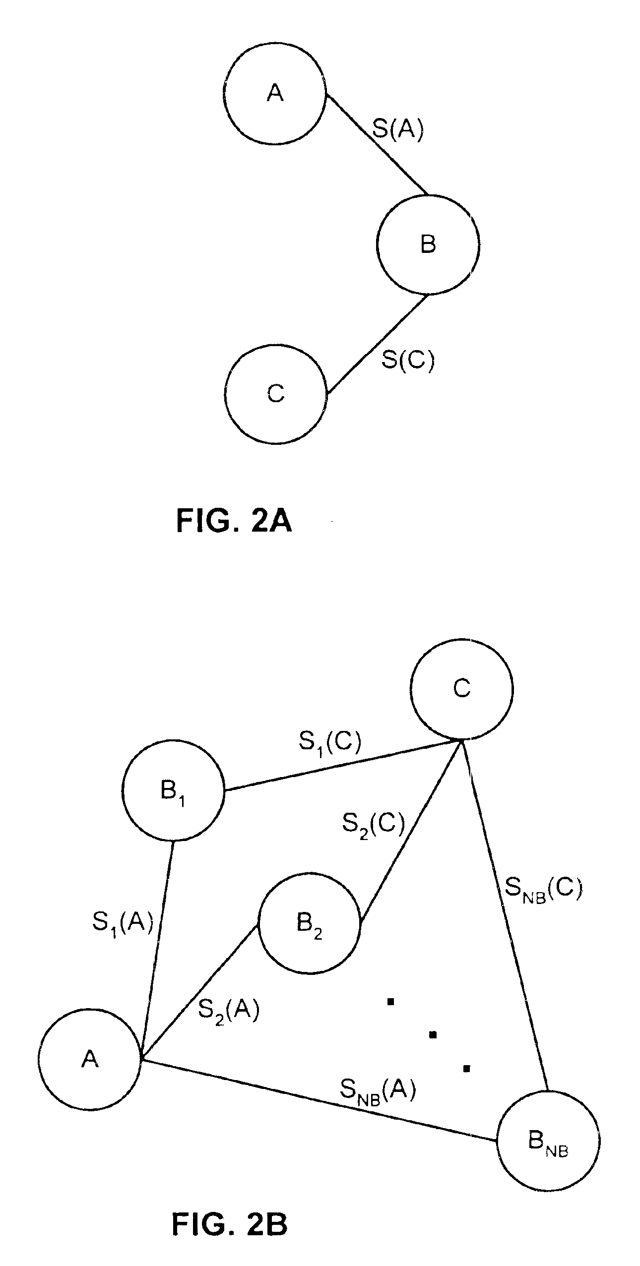
[0030]The transitive property is illustrated conceptually in FIGS. 2A and 2B. Referring to FIG. 2A, instead of directly comparing the biometric data of sample A with the biometric data of sample C, the data of samples A and C are independently compared with a third basis or reference sample B. By virtue of the transitive property, if sample A has a high score S(A) against sample B and sample C also has a high score S(C) against sample B, then there is a high likelihood (i.e. there is an increased probability) that sample A has a high score against sample C. In the present invention, the transitive property is applied to an underlying match algorithm using a plurality of basis sample elements, shown as B1 to BNB in FIG. 2B (and contained in database DBB in FIG. 1). As described in detail below, recognition may be much more rapidly established by comparing the scores S(A) of sample A with each basis element B1 to BNB to the scores S(C) of sample C with the same basis elements, as fundamentally illustrated in FIG. 2B. In this manner, the score vectors S(A) and S(C) each provide encoded recognition information that may be used to measure nearness in a biometric vector space created by the basis elements B1 to BNB. Different recognition measures for determining the similarity or nearness of the score vector S(A)={S1(A), S2(A), . . . SNB(A)}T and the score vector S(C)={S1(C), S2(C), . . . SNB(C)}T can be used. For example, M ( A , C ) = 1 NB ∑ NB [ S I ( A ) - S I ( C ) ] 2
where ΣNB denotes a sum over the basis set DBB with I=1 to NB and S1(A) refers to the raw score of sample A with the I'th basis element. Other measures which determine nearness based on, for example, Euclidean distance or Manhattan distance are also possible. Generally, the smaller the value of M(A,C), the closer encoded vectors S(A) and S(C) are in the biometric vector space created by the basis elements B1 to BNB, and the higher the probability of a match or recognition between samples A and C.
[0031]However, because the set of basis elements is a finite set, a transitive recognition measure—such as M(A,C)—that determines the similarity between the scopes S(A) and S(C) does not produce optimal results for the classification or recognition of biometrics. In accordance with the present invention, transitive recognition system 100 performs a first sample space rotation, and preferably also second recognition space rotation, on raw scores obtained from underlying recognition system 150 to provide a highly compressed encoded vector that enables rapid matching and recognition to be performed with an improved transitive measure. The method of operation of transitive system 100 is depicted in flow chart form in FIGS. 3-6 and is described below.
[0032]FIG. 3 shows a preferred method of operation of sample space rotation module 110 of transitive recognition system 100 of FIG. 1. Referring to FIG. 3, transitive system 100 must initially select the basis elements B1 to BNB in database set DBB. Each basis element B1 represents the biometrics of a different individual and may be selected according to different criteria. For example, the basis set DBB may be taken from representatives of the population having the highest overlap (or scores) with non-basis probe biometric samples. On the other hand, the basis set DBB may be taken from representatives of the population having minimal overlap with each other, thereby helping to ensure that the vector space created by the basis set covers the extreme boundaries of the biometric pace well. As a further alternative, the elements in the basis set DBB may be selected at random. In the specific context of face recognition, all three of the above basis constructions were attempted, and the randomly constructed basis set provided the best recognition during out-of-sample testing (i.e. testing on biometric samples not in basis set DBB). As a result, a randomly selected basis set is preferably selected in step 310, at least in the case of face recognition.
[0033]However, since it is difficult to determine a truly random subset over a biometric population, there is a strong possibility, particularly for small basis sizes, the certain parts of the biometric space may be over-represented and certain parts may be under-represented. The existence of over-represented regions of the biometric space leads to over-discrimination in favor of biometric samples in the over represented space. Conversely, there is under-discrimination against biometric samples in the under-represented regions of the biometric space. As described below, in view of the inherent limitations of a finite size basis DBB, transitive system 100 provides an improved transitive recognition measure that maps the “raw” scores S(A) and S(C) into newly constructed biometric vector spaces.
[0034]To determine such an improved measure that can be used to denote the distance between two biometric samples in biometric space, a sample database DBS is used, and so is selected at step 320 in FIG. 3. The database DBS includes NS samples, A1 to ANS, each of which is out-of-sample with respect to the basis set elements in DBB (the samples A1 to ANS in database DBS may also be referred to as test samples). At step 330, for each basis element B1 to BNB, and each representative A1 to ANS in database DBS, the score S(A) is calculated using the underlying matching algorithm A NB×NB covariance matrix COV is constructed, as shown in step 340, where the (I, J)'th element of the matrix COV is given by COV IJ = 1 NS 2 ∑ NS [ S I ( A ) - M I ] · [ S J ( A ) - M J ]
and where ΣNS denotes a sum over DBS with A=1 to NS, and with M1 (and similarly M3) given by: M I = 1 NS ∑ NS S I ( A )
It should be noted that the matrix COV is computed using out-of-sample data, i.e. the scores S(A), allowing the transitive property to be exploited. Furthermore, it will be appreciated that the covariance matrix COV provides a convenient way of determining and assessing how the dispersion of the basis elements is related. However, although the covariance matrix COV is preferably used to generate sample space scores as described below, it will be appreciated that other measures of dispersion (i.e. other than variance) may also be used.
[0035]If each of the raw space basis element directions I and J, where I≠J, are completely de-correlated, then the off-diagonal elements of COV would be zero, and the I'th diagonal elements would equal the variance in the I'th basis direction (with the variance σ2 equalizing the square of the standard deviation σ). As will be appreciated, however, in the “raw” biometric vector space of DBB the basis directions I and J will generally be correlated to varying degrees. The COV matrix is real and symmetric (COV=COVT) and can hence be diagonalized into a form that reveals the matrix's eigenvectors φ1 (i.e. φ1 to φNB) and corresponding eigenvalues λ1 (i.e. λ1 to λNB), as indicated step 350. Specifically, a linear transformation that diagonalizes COV provides a matrix of eigenvectors. The diagonalization may be accomplished by a numerical technique such as singular value decomposition or a Householder-QR (or Householder-QL) decomposition.
[0036]Since COV is real symmetric, its eigenvalues are non-negative and its eigenvectors form a complete orthogonal set. The resulting eigenvectors φ1 denote the linearly independent (or principal component) directions or modes E1 in a biometric sample space S1 and the eigenvalues λ1 indicate the square of the “width” of the distribution of samples in those directions, i.e. the I'th eigenvalue represents the variance in the I'th direction. At step 360, the eigenvectors and values are ordered in terms of decreasing eigenvalue λ1 such that λNB≦λNB-1 ≦. . . ≦λ2≦λ1.
[0037]It should be noted that the raw scores S1(A) may be processed before being used to generate COV or, more generally, to construct the sample space S1. For example, the scores S1(A) may each have a mean subtracted from them to compensate for certain condition (e.g. lighting) during the acquisition of samples. Furthermore, more than one score may be used for each person or object represented in DBS.
[0038]A biometric sample space rotation matrix C is determined, at step 370, by
C=[φ1φ2. . . φNB]
where C maps between the raw biometric space and the biometric sample space S1. The rotation matrix C denotes the most important directions or modes E1 in biometric S1 space, i.e., the directions that best separate one sample from another and hence provide a maximal discrimination between biometric samples. At step 380, a scale for each direction E1 in the biometric sample space S1 is also determined and given by
D1=(λ1)1/2DNB≦DNB-1≦. . . . ≦D2≦D1
with D1 representing the standard deviation in the linear independent direction E1. Again as indicated, the sample space S1 is ordered with the largest scales D1 indexed before the smaller scales. The scales D1 are used to normalize the effect of each direction E1 in a sample space score generated at step 390 is: SE I ( A ) = 1 D I ∑ NB C · S J ( A )
where ΣNB denotes a sum over the initial basis set DBB with J=1 to NB, and (SE1(A) refers to the sample space score of sample A with the E1 direction or mode in the biometric sample space (i.e., rotated from the raw biometric space). It will be appreciated that due to the normalization with the scales D1, the entire biometric sample space S1 becomes a normalized hyper-sphere.
[0039]Small D1 represent less relevant directions E1 in which linear combinations of the scores in the basis have the least ability to discriminate between samples in the database DBS. These low scale directions may be also be thought of as “fine-tuned” directions to the database DBS, and therefore are not suitable for biometric discrimination. As a result, the recognition method and system of the present invention preferably truncates the biometric sample space S1 by eliminating modes E1 with small scales D1, before generating a transitive sample space measure ME(A,C). FIG. 4 illustrates, in flow chart form, a preferred method of operation of sample space truncation and measure module 120 in transitive recognition system 100. To determine an appropriate cutoff in E1 modes, a second out-of-samples database DBS2 may be used (i.e. DBS2 is out-of-sample with respect to both DBB and DBS). Database DBS2 is therefore selected at step 410. The samples pace scores SE1(A) for each sample A in DBS2 are calculated for each mode E1 of the biometric sample space S1 in step 420. At step 430, the standard deviation ρS21 of the distribution of the scores for each mode is then determined, at step 430, and divided by the corresponding D1 at step 440. If the vector rotation for that mode generalizes, the ratio σS21/D1 should be close to 1.0, for example from about 0.9 to 1.1. However, as this ratio approaches 1.3-1.4, the vector analysis clearly fails for the out of sample data in DBS2. It will be appreciated that increases in the ratio σS21/D1 closely correspond with decreases in D1 for the ordered modes E1 in biometric sample space. Thus, an appropriate cut-off may be taken for sample space modes E1 for which this ratio begins to exceed some value within the range 1.1 and 1.3, as indicated at step 450. In one preferred embodiment, a cut-off ratio of approximately 1.25 is selected, corresponding roughly to three standard deviations beyond the expected value of 1.0. In this manner, at step 460, a number of the E1 having the lowest D1 are simply truncated, based on the ratio cut-off above, from the biometric sample space S1 thereby further increasing the robustness of the method and system of the present invention to out of sample biometric data (i.e. data out-of-sample with respect to both DBB and DBS). The number of principal directions or modes E1 remaining after truncation is denoted as NE, and an improved measure for biometric discrimination in the truncated sample space S1 is given, as indicated at step 470, by ME ( A , C ) = 1 NE ∑ NE [ SE I ( A ) - SE I ( C ) ] 2
Again, other similar (Euclidean, Manhattan, etc.) measures of the distance between biometric vectors A and C in truncated sample space can alternatively be used.
[0040]The sample space into which the rotation matrix C maps, as constructed by modules 110 and 120 in system 100, is still not optimal for performing biometric or object recognition. This is because the sample space measure ME(A,C) does not take into account the possibility that the same object or individual may undergo variations in appearance that, insofar as recognition matching is concerned, should be disregarded. As a result, transitive recognition system 100 provides for a further rotation of the sample space scores SE(A) into a recognition space SR1. The recognition space SR1 further takes into account the possibility that in the sample space S1, there may be directions associated with changes of the same individual or object, such as a change of expression in a face, or a change of orientation or scale of a fingerprint. As indicated, these directions in sample space are or should be directions of zero measure size in recognition space. Stated another way, the recognition space SR, includes biometric sample space directions ER1 that differentiate between different individuals.
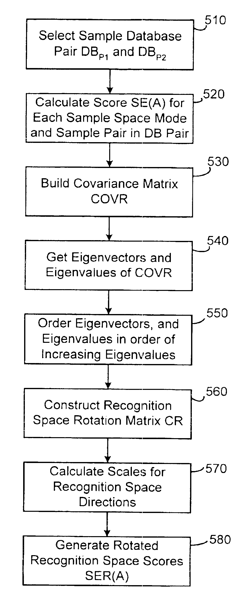
[0041]A preferred method of operation of recognition space rotation module 130 is illustrated in FIG. 5. To construct the biometric recognition space SR1, a database pair, defined as two databases DBP1 and DBP2 each having a different biometric sample of the same NP individuals, is selected at step 10. That is, the samples between databases for the same database index differ only by a re-sampling of the same individual, for example at different times, in different surroundings, and/or at different orientations. As the database entry changes in DBP1 and DBP2, the individual sampled changes as well. The databases DBP1 and DBP2 may also be referred to as common object databases. Recognition space SR1 is built on biometric sample space S1 by using the database pair and, in effect, identifying the directions in biometric sample space that best differentiate between individual.
[0042]Referring to FIG. 5, at step 520, for each mode E1 (i.e., in the truncated sample space modes) and each sample pair in the databases DBP1 and DBP2, the sample space scores SE1(A1) and SE1(A2) are calculated, where A1 and A2 are representative samples of the same individual (or object). It should be noted that the biometric sample cores SE(A) (as opposed to the raw score S(A)) is used. A NE×NE covariance matrix COVR is constructed , as shown in step 530, where the (I, J)'th element of the matrix COVR is given by COVR IJ = 1 2 NP 2 ∑ NP [ SE I ( A1 ) - SE I ( A2 ) ] · [ SE J ( A1 ) - SE J ( A2 ) ]
where ΣNP denotes a sum over the database pair DBP1 and DBP2 with A1, A2=1 to NP. The matrix COVR is again real and symmetric and can be decomposed or diagonalized into a form that reveals the matrix's eigenvectors φR1 (i.e., φR1 to φRNE) and corresponding eigenvalues λR1 (i.e., λR1 to λRNE), as indicated at step 540. As with the diagonalization of COV, singular value decomposition or Householder-QR techniques may be used to diagonalize COVR.
[0043]The resulting eigenvectors φR, form a complete orthogonal set and denote the linearly independent directions ER1 in biometric recognition space SR1. The eigenvalues λR1 are non-negative and represent the variance or the square of the “width” of the distribution of samples in the directions ER1. At step 550, the eigenvectors and values may be denoted or ordered in terms of increasing eigenvalue λR1 such that λR1≦λR2. . . ≦λRNE-1≦λRNE.
[0044]At step 560, a biometric recognition space rotation matrix CR is determined, at step 560, by
CR=[φR1φR2. . . φRNE]
where CR maps between the biometric sample space S1 and the biometric recognition space SR1. The matrix CR denotes the most important directions ER1 in recognition space SR1, the directions that best separate one person (or object) from another, and hence provide a maximal discrimination between individuals. At step 570, a scale DR1 for each direction ER1 in the biometric recognition space is determined and is given by
DR1=(λR1)1/2DR1≦DR2≦. . . ≦DRNE-1≦DRNE
with DR1 representing the standard deviation in the ER1 linear independent direction in recognition space SR1. The directions and scales are ordered with the smallest scales DR1 indexed before the larger scales.
[0045]The input elements of the COVR matrix, SE1(A), are representatives in each sample space direction E1 of distributions with a variance equal to 1 (normalized to 1 by dividing by D1). As indicated, the sample space S1 corresponds to a normalized hyper-sphere of “size” 1 in all sample space directions E1. If the underlying algorithm used in the raw recognition score system 150 is unable to perform recognition, then the diagonalized elements of COVR (i.e. its eigenvalues λR1) will be approximately equal to 1, since this is the variance in the biometric sample space S1, and the rotation performed by matrix CR does not affect this property. On the other hand, if the underlying raw score algorithm is able to perform recognition, then the distribution in biometric sample space S1 of the difference between scores of samples of the same person (i.e. SE1(A1)-SE1(A1)) is smaller than if the samples correspond to different people. Thus, in the recognition space analysis, the space is ordered with respect to the smallest scales DR1 first, since the smaller the scale, the better the direction or mode ER1 is for recognition.
[0046]A rotated recognition space score is generated at step 580 as follows: SER I ( A ) = ∑ NE CR · SE J ( A )
where ΣNE denotes a sum over the truncated samples space modes E1 with J=1 to NE and SER1(A) refers to the recognition space score of sample A with the direction or more ER1 in the biometric recognition space.
[0047]In the alternative to constructing the recognition space SR1 by calculating and diagonalizing a COVR matrix as described above, other methods and techniques may be used on the projections of sample database pairs from DBP1 land DBP2 on to sample space S1. Furthermore, other common object databases (e.g. DBP3DBP4, etc.) having additional distinct samples of the same objects or persons in DBP1 and DBP2 may also be used to construct recognition space. Some of these discriminant techniques are linear, such as Fisher's Linear Discriminant analysis which takes a difference between vectors in sample space S1, and then applies Fisher analysis along with subsequent diagonalization techniques; while other discriminant techniques are non-linear, such as algorithms based on two or three layer neutral networks. These and other suitable techniques are described by Bishop in “Neutral Networks for Pattern Recognition” (Clarendon Press: Oxford, 1995), the contents which are incorporated herein by reference.
[0048]When the scales DR1 for each direction or mode ER1 in recognition space are approximately equal to 1, this is indicative of directions in which linear combinations of the scores in the recognition space basis have the least ability to perform recognition in the databases DBS, DBP1, and DBP2. These directions may again be considered “fine-tuned” directions to the databases DBS, DBP1, and DBP2 and should not be used for person or object discrimination. Recognition space truncation and measure module 140 in transitive system 100 therefore preferably a carries out a truncation of the recognition space directions ER1 before providing a transitive recognition space measure MER(A,C).
[0049]A preferred method of operation of module 140 is shown in FIG. 6. To determine an appropriate cutoff in modes, a third out-of-sample database DBS3 (i.e. DBS3 is out-of-sample with respect to DBB,DBS, DBP1, DBP2, and DBS2) whose samples correspond to different individuals or objects than those in other databases, may be used. Such a database DBS3 is selected at step 610. The recognition space scores SER1(A) for each sample A in DBS3 are calculated for each mode ER1 of the biometric recognition space SR1 in step 620. As described above, since the samples in DBS3 correspond to different individuals or objects than those in other databases, no recognition should occur, and ideally the scales DR1 should be one. Referring back to FIG. 6, the standard deviation σS31 of the distribution of the scores for each mode is then determined, at step 630, and divided by the corresponding DR1 at step 640. If the vector rotation for that mode generalizes, the ratio σS31/DR1 should be close to 1.0, for example from about 0.9 to 1.1. In contrast, as this ratio approaches 1.3-1.4, the vector analysis clearly fails for the out of sample data in DBS2. It will be appreciated that in this case, increases in the ratio σS31/DR1 considerably beyond 1.0 closely correspond with increases in DR1 considerably beyond 1.0 for the modes ER1 in biometric sample space.
[0050]Thus, an appropriate cut-off may again be taken for recognition space modes ER1 for which this ratio begins to exceed some value within the range 1.1 and 1.3, as indicated at step 650. Again, in a preferred embodiment, a cut-off ratio of approximately 1.25 may be selected, corresponding to about three standard deviations beyond the expected value of 1.0. In this manner, at step 660, a number of the ER1 generally having the highest D1 are truncated, based on this ratio cut-off, from the biometric sample space SR1. As a result, the robustness of the method and system of the present invention to out-of-sample biometric data (i.e. data out-of-sample with respect to both DBB and DBS) is further increased. The number of principal directions or modes ER1 remaining in the truncated recognition space SR1 is denoted as NER. An improved measure for biometric discrimination in the truncated recognition space SR1 is given, as indicated at step 670, by constructing. MER ( A , C ) = 1 NER ∑ NER RF I · [ SER I ( A ) - SER I ( C ) ] 2
wherein, for example, RF I = 1 DR I 2 - 1 = 1 λ R I - 1
The recognition factor RF1 is used to ensure that, as the mode ER1 has lessening recognition capability, DR1 approaches 1, so that the mode ER1 does not contribute to the measure. The recognition factor R1 is one of many possibilities, and generally RF1 only needs to ensure that modes ER1 that are unable to perform recognition do not contribute, and modes ER1 that contribute strongly to recognition receive more weight. The above implementation of recognition factor RF1 provides one such simple solution. In addition, other measures of the nearness of points or vectors SER(A) and SER(C)) in recognition space SR1 can alternatively be constructed.
[0051]The recognition space measure MER(A,C) is a main result of the transitivity principles outlined above. The construction of the recognition space SR1 (and the sample space S1) provides a vector space in which encoded biometric or object sample vectors SER can exist. The encoded vectors are generated by taking the underlying or core recognition algorithm in system 150 and the database DBB of basis elements to first provide the raw scores S(A)={A1(A), S2(A), . . . SNB(A)}T of a probe or test sample A. The vector S(A) is then mapped or rotated into the sample space scores SE(A)={SE1(A), SE2(A), . . . SENE(A)}T to provide a vector encoded in sample space. Preferably, the sample space encoded vector SE(A) is then further mapped or rotated into the recognition space scores SER(A)={SER1(A), SER2(A), . . . SERNER(A)}T. Thus, the distance or nearness between any two recognition space encoded vectors SER(A) and SER(C) can be measured with a suitable measure MER(SER(A), SER(C)) which can equivalently be given as EMRA(A,C) as described above. When it is desired to match a probe person (or object) with one of a number of known persons (or objects), the encoded score of a known person that provides the lowest measure score of MER(A,C) generally determines a match or recognition.
[0052]Transitivity matching in this manner provides a means for pre-encoding biometric match information from each set of raw biometric (or object) sample data, such as a face image or a fingerprint. With the transitive recognition method and system of the present invention, the time required for the recognition system to perform matching is dramatically reduced, i.e., the time required to generate a recognition space encoded vector SER(A) for a probe sample A and compare it, using MER(SER(A), SER(C)), to other similarly encoded known samples C is dramatically reduced. In addition, the size of the encoded biometric vectors or templates SER(A) is also significantly reduced compared to the size of raw score vectors S(A).
[0053]In effect, the sample space S1 is a linear approximation to the non-linear recognition properties of the underlying core algorithm in system 150, however the recognition space SR1 has “knowledge” of recognition beyond that provided by the initial algorithm in system 150. Although the transitive system 100 preferably constructs (and encodes object or biometric vectors in) recognition space SR1, in some cases constructing (and encoding vectors in) only the sample space S1 may be beneficial. For example, this may be the case where object recognition is being performed on objects that do not generally vary over time. Also, while truncating each of the sample and recognition spaces is preferred, truncated is not required to obtain the benefits and advantages of the present invention. The major advantage of more rapidly matching objects is due largely to the pre-calculation of scores and the exploitation of the transitive property.
[0054]The sample space may be populated via any reasonable score generator, and there are no special requirements for the underlying score generation algorithm in system 150. For example, most, if not all, face recognition algorithms can be used to provide raw score inputs to transitive system 100 of the present invention. Similarly, most imaging based fingerprint algorithms may also be used to provide raw score inputs to transitive system 100. Furthermore, the speed of many other biometric and object recognition algorithms may also be significantly improved by the transitive system and method of the invention. The principal criterion is that the raw score algorithm in the underlying recognition system 150 must be able discriminate between individuals or objects, as required by the application.
[0055]In general, the accuracy of the measure MER(A,C) of the present invention follows the accuracy of the underlying algorithm in system 150, as the number of elements in the basis database DBB becomes sufficiently large. For example, in a face recognition application, the basis database DBB preferably includes 200 or more basis samples. As a result, there is little or no loss of accuracy with respect to the underlying match algorithm in system 150. Furthermore, in the process of constructing the recognition space SR1, recognition data is provided by way of the database pairs DBP1 and DBP2. This additional data may serve to improve the accuracy of the initial core algorithm.
[0056]In one preferred embodiment of the present invention, for a face recognition application, raw recognition score system 150 includes components of the FaceIt® software developer kit available from Vision is Corporation of Jersey City, N.J. For example, system 150 may include the function CFACE:LoadFace of the FaceIt® developer kit which generates face templates or faceprints from video images using a Local Feature Analysis algorithm. In addition, system 150 may include the function CFACE::IdentifyPerson of the FaceIt® developer kit which generates a representation, i.e., a digital faceprint, for faces and performs matching between different representations to generate a raw matching score.
[0057]In a specific example of such a face recognition implementation, the following database sizes were used: DBB included 200 samples of different people; and DBS, defining biometric sample space, contained 1,000 samples of different people. The truncated biometric sample space included the first 128 modes E1 (i.e., the 128 modes having the largest D1). The database pair DBP1 and DBP2 included sample pairs of 1000 individuals, and the truncated biometric recognition space included the first 80 modes ER1 (i.e., the 80 modes having the largest DR1). In this implementation and with these parameters, the time required to encode and match a biometric sample is roughly one second, i.e., 200 matches per second for a raw score vector S(A) on a 500 MHZ Pentium III computer system.
[0058]After construction of the SER(A) vector, which in its final form is 80 dimensional, the SER(A) vector may be projected onto a byte scale for each of its 80 components. The byte scale ranges from 0-255 and preferably corresponds to 6 DR1 lengths. All rotations and divisions are pre-computed into each vector SER(A). Using system 100 of the present invention, the transitive recognition space measure calculation MER(A,C) is carried out at a rate of 47 million per minute on the same computer system. This represents a many-fold improvement in recognition or matching speed. In addition, the template used for the initial matching S(A) has a size 3.5 KBytes. The final temperature size of SER(A) is reduced to 80 Bytes. As will be appreciated, these dramatic improvements in speed and storage requirements are highly advantageous.
[0059]While the invention has been described in conjunction with specific embodiments, it is evident that numerous alternatives, modifications, and variations will be apparent to those skilled in the art in light of the foregoing description.
Login to view more PUM


Description & Claims & Application Information
We can also present the details of the Description, Claims and Application information to help users get a comprehensive understanding of the technical details of the patent, such as background art, summary of invention, brief description of drawings, description of embodiments, and other original content. On the other hand, users can also determine the specific scope of protection of the technology through the list of claims; as well as understand the changes in the life cycle of the technology with the presentation of the patent timeline. Login to view more.
Login to view more Similar technology patents
Method and system for reliable broadcast or multicast communication in wireless networks
InactiveUS20070268868A1Efficient utilization of channelReduce timeBroadcast service distributionRadio/inductive link selection arrangementsControl channelMulticast communication
Owner:SAMSUNG ELECTRONICS CO LTD
Centrifuge Loading Process Within An Automated Laboratory System
ActiveUS20090318276A1Reduce timeDispersed particle separationCentrifugal force sediment separationEngineeringTime to result
Owner:SIEMENS HEALTHCARE DIAGNOSTICS INC
GNSS receiver using signals of opportunity and assistance information to reduce the time to first fix
ActiveUS20090322601A1EliminateReduce timeBeacon systemsSatellite radio beaconingPhase correlationSatellite
Owner:NOVATEL INC
Panel with a slider
Owner:VÄLINGE INNOVATION AB
Classification and recommendation of technical efficacy words
- Reduce time
- Reduce in size
Multi-component vascular device
Owner:ST JUDE MEDICAL CARDIOLOGY DIV
Patient specific anatomically correct implants to repair or replace hard or soft tissue
InactiveUS20060136058A1Reduce timeReduce amount of timeMedical simulationAdditive manufacturing apparatusPatient specificLiving body
Owner:PIETRZAK WILLIAM
Apparatus and method for prediction and management of subject compliance in clinical research
ActiveUS6879970B2Increase statistical powerReduce timeTherapiesDigital computer detailsClinical researchData science
Owner:ERESTECH
Deoxyribonucleic acid measuring apparatus and method of measuring deoxyribonucleic acid
InactiveUS20070059741A1Accelerate reaction cycleReduce timeMaterial nanotechnologyBioreactor/fermenter combinationsForeign matterPhosphate
Owner:HITACHI LTD
Microprocessor controlled ambulatory medical apparatus with hand held communication device
ActiveUS20050010269A1Enhance capacityReduce in sizeEnergy efficient ICTElectrotherapyTelemetry EquipmentBiomedical engineering
Owner:MEDTRONIC MIMIMED INC
Method and system for generation and playback of supplemented videos
ActiveUS20090276805A1Reduce in sizeGood targetTelevision system detailsMultimedia data queryingAggregate dataObject based
Owner:AIBUY INC
Device and method of arthroscopic knee joint resurfacing
InactiveUS20050137708A1Reduce in sizeLoad shareSuture equipmentsSurgical needlesFemurCancellous bone
Owner:CLARK RON
System and method for selective processing of digital images
InactiveUS7121469B2Reduce in sizeCharacter and pattern recognitionVerifying markings correctnessDigital cameraDigital image
Owner:HANGZHOU HIKVISION DIGITAL TECH
Making electrical components in handle wafers of integrated circuit packages
ActiveUS9165793B1Reduce in sizeMaximization of size and capacitySemiconductor/solid-state device detailsSolid-state devicesRedistribution layerSemiconductor
Owner:INVENSAS CORP