Hardwareless Mount For Product Display

a technology for product display and hardware, applied in the field of products display, can solve the problems of cumbersome card replacement, card asymmetry, unsightly point of purchase display, etc., and achieve the effect of convenient installation and removal

Inactive Publication Date: 2020-05-28
LLOYD GERSTNER & PARTNERS
View PDF7 Cites 0 Cited by
  • Summary
  • Abstract
  • Description
  • Claims
  • Application Information

AI Technical Summary

Benefits of technology

[0007]In view of the above deficiencies, it is an object of the present invention to provide an improved point of purchase display system wherein product information mounts are easily installable and removable from the display.

Problems solved by technology

The existing displays in which component information cards are attached directly to shelving for the component have drawbacks in that the cards are cumbersome to change, replace or rearrange such as when inventory changes.
For example, if adhesive or hook / loop fasteners are used to attach the cards directly to display shelving or to mounts affixed to the shelving, the cards have a tendency to be detached from the shelving as a result of consumer traffic and inadvertent contact.
Moreover, the removal and replacement of the cards results in an unsightly point of purchase display due to the exposed adhesive or hook / loop fasteners left behind on the shelving.
In addition, if mounts are used to attach the cards and / or component samples to the shelving by hardware, there is difficulty in repositioning the mounts, such as when components on the point-of-purchase display are rearranged.
Such a system, however, also has drawbacks.
In particular, an intermediate mount, i.e., a mount that is positioned in between two or more adjacent surrounding mounts, cannot be readily replaced without first sliding adjacent mounts off of an end of the rail, replacing the intermediate mount, and then re-installing the adjacent mounts, again, by slidable engagement.
Such activity is time consuming and cumbersome.

Method used


Image

  • Hardwareless Mount For Product Display
  • Hardwareless Mount For Product Display
  • Hardwareless Mount For Product Display

Examples


first embodiment

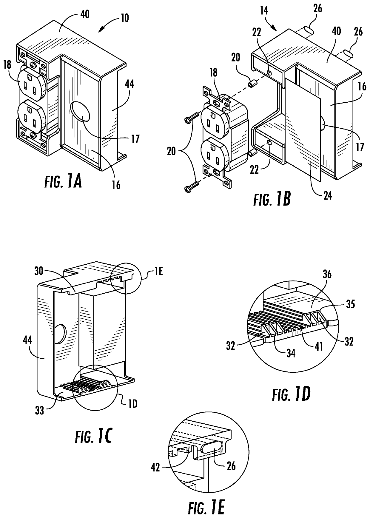
[0029]FIGS. 1A-1E are perspective, exploded, rear perspective and detailed views, respectively, showing a mount, i.e., holder 10, for displaying a product sample with associated graphics to consumers in a point-of-purchase display, according to the present invention.

[0030]The mount 10 includes a sample holder portion 14 for holding a sample product 18 (such as, by way of non-limiting example, an electrical outlet accessory), which can be seen in FIGS. 1A and 1B. The mount 10 also includes a graphics holder portion 16 for holding a graphics card 24. The graphics card 24, shown, for example, in the exploded view of FIG. 1B, bears indicia of the product 18, such as a picture of the product 18, price information, specifications, etc.

[0031]The sample holder portion 14 is configured to provide an area to receive the sample product 18. As can be seen in the exploded / disassembled view of FIG. 1B, the receiving area includes mounting holes 22 for receiving fasteners 20, such as screws and as...

second embodiment

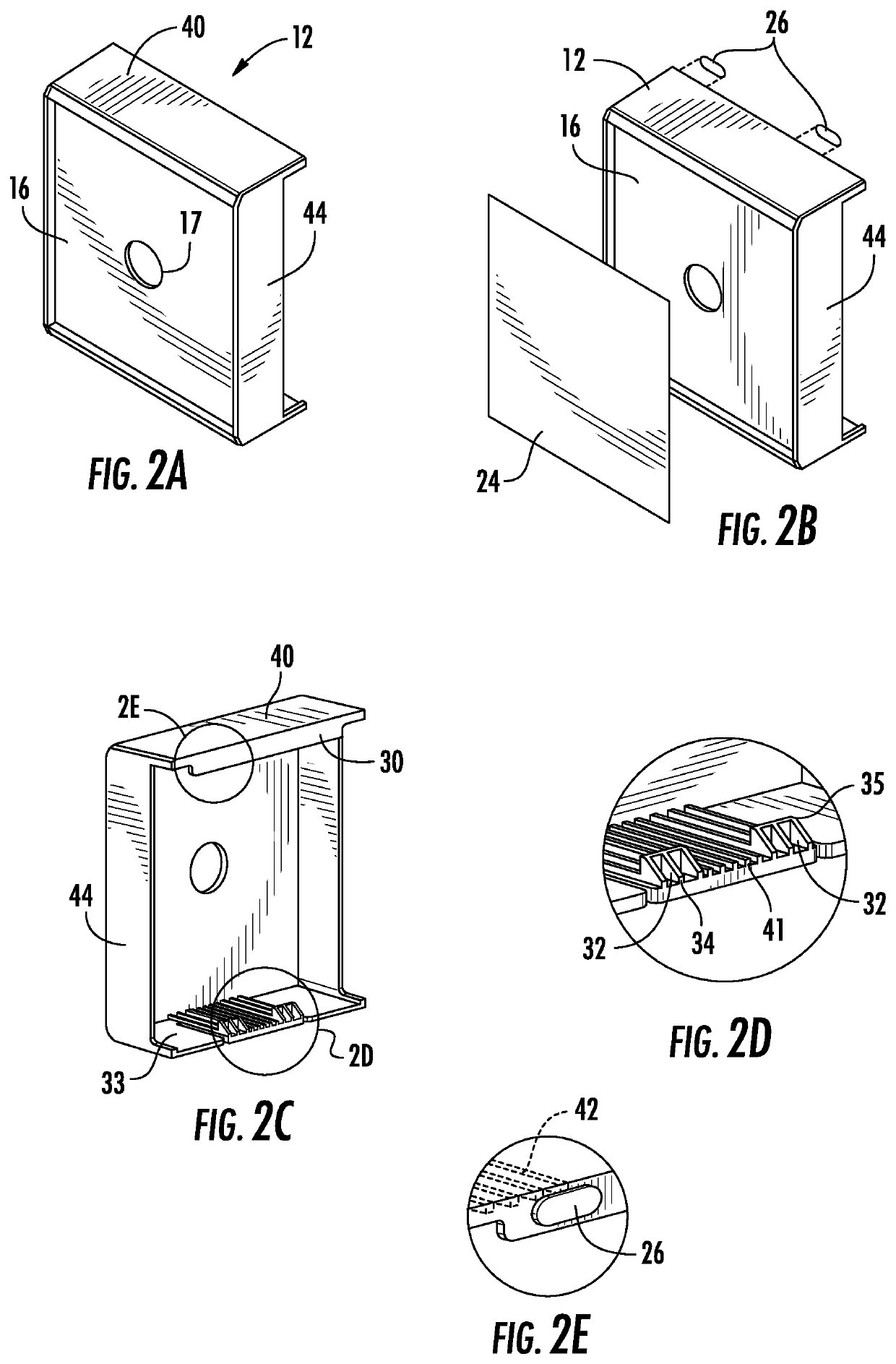
[0042]FIGS. 7A-7E are various views illustrating structures provided at inner portions of the upper surface 40 and the bottom surface 33 of the mount 12 according to the The ramps 32, best seen in FIG. 7B, are located at a middle portion of the bottom surface 33 and are separated from sections on either side of the middle portions by cutouts 46, 48 (see FIGS. 7A and 7B). FIG. 7A is a perspective view from below, in which the cutouts 46, 48 are visible. The cutouts 46, 48 allow the middle portion of the bottom surface 33 containing the ramps to flex downwardly when the mount is attached to the rail, as explained below. As a result, it is preferable to locate the bottom surface strengthening ribs 41 of the bottom surface 33 in the middle portion of the bottom surface 33.

[0043]FIGS. 7D and 7E are side and rear views, respectively, of the mount 12. The side view FIG. 7D illustrates the lip 30 having an angle approximately perpendicular to the front face of the mount 12. Together, the v...


PUM


Abstract

A snap mountable holder releasably attachable to a point of purchase display, the display having a beam proximate products for purchase, includes: a housing; a top lip at a top of the housing and configured to engage a top edge of the beam; and a bottom lip engaging a bottom edge of the beam. One of the top lip and the bottom lip has a non-slip grip engageable with the beam, and the other of the top lip and bottom lip has an enforced region and an unenforced region isolated from each other. The enforced region contains a snap-in feature, the housing being dimensioned in relation to a distance between the top edge and the bottom edge of the beam such that when the non-slip grip is engaged with the beam, the housing is rotatably engageable to the beam about the longitudinal axis of the beam by the snap-in feature.

Description

CROSS-REFERENCE TO RELATED APPLICATION[0001]This application claims priority under 35 U.S.C. 119(e) from U.S. Provisional Patent Application No. 62 / 771,437, filed Nov. 26, 2018, the contents of which are incorporated by reference herein in their entirety.BACKGROUND OF THE INVENTION1. Field of the Invention[0002]The present invention is directed to a display for products and, more particularly, to product sample mounts for attaching product samples and / or product graphics to a point of purchase display without the need for tools or attachment hardware.2. The Related Art[0003]Displays for product samples are well known, particularly in connection with hardware, electrical components, plumbing couplings, and the like, as would typically be found in hardware retail stores. In such establishments, shelving is provided for containing inventory of the various products to allow consumers to select the desired products from the display. Proximate the location of the inventory for each produc...

Claims


Application Information

Patent Timeline
Patent Type & Authority Applications(United States)
IPC IPC(8): G09F3/20G09F7/18
CPCG09F3/204G09F7/18G09F2007/183
Inventor KIM, SUNGWOOGERSTNER, ROBERT
Owner LLOYD GERSTNER & PARTNERS
Why Eureka
Try Eureka