Probe for monitoring the surface level of a fluid in a vessel and a method of installing the probe in the vessel

a technology for monitoring the surface level of fluids and probes, which is applied in the direction of level indicators by pressure measurement, level indicators by physical variable measurement, measurement devices, etc., can solve the problems of affecting the accuracy of the measurement, the mechanical strength of the wires is not good, and the fluid consistency or dry material content is sensitiv

Inactive Publication Date: 2017-09-05
SULZER MANAGEMENT AG
View PDF15 Cites 0 Cited by
  • Summary
  • Abstract
  • Description
  • Claims
  • Application Information

AI Technical Summary

Benefits of technology

[0020]Thus, an object of the present invention is to eliminate at least one of the above mentioned drawbacks or problems by a novel probe for monitoring the surface level of a fluid in a vessel.
[0022]A further object of the present invention is to develop a novel probe for monitoring the surface level of a fluid in a vessel, the probe being easily installable and maintainable from outside the vessel and being positioned in the vessel such that it does not interfere in the flow dynamics in the vessel and does not easily get damaged in the vessel.
[0027]b. It is easy to utilise mass- or series-production in the manufacture of the apparatus,
[0028]c. The installation of the apparatus is simple and takes very little time,
[0034]i. The maintenance of the apparatus is easy, as the apparatus may be easily removed from the vessel.

Problems solved by technology

Capacitive sensors or wires are widely used, but they are very sensitive to the consistency or dry material content of the fluid.
They also collect dirt and lose their sensitivity fairly quickly.
Additionally, they, especially the wires are mechanically weak, i.e. they may loosen or break, and, at worst, end up in the fluid and along with the fluid in the pump and in the further process.
Radiometric measurements have their own downsides, i.e. limited acceptance due to the use of the radiation source, limited operational time, required permits as well as other specific regulations.
As discussed above, all devices used, in one way or another, for measuring a surface level of a fluid in a vessel have their own problems and downsides.
There are additional problems when the fluid is not a liquid that behaves like water.
The fluid may be lumpy whereby the surface topography is very uneven.
A yet further problem in the prior art devices or apparatus used in monitoring the surface level in a vessel is that they are either devices that have been integrated into a structure, for instance a wall, of the vessel, or they may be installed or repaired only by entering the interior of the vessel.
Yet another problem in some prior art devices is that the probe is arranged to be installed in the vessel via an opening in the top cover of the vessel.
If the height of the vessel is several meters and the level of the fluid surface is supposed to fluctuate somewhere in the middle part of the vessel the required length of the probe makes the probe very vulnerable unless it is built sturdy enough.
Another problem relating to the probe arranged to the top cover of the vessel may be seen in vessels where there is, in practice, no top cover at all, but the vessel is formed of a bend at the top thereof and a downflow pipe both having the same constant diameter.
In such a case, the flow in the vessel takes place over the entire cross section of the vessel, and would subject a top arranged probe to considerable stress.

Method used


Image

  • Probe for monitoring the surface level of a fluid in a vessel and a method of installing the probe in the vessel
  • Probe for monitoring the surface level of a fluid in a vessel and a method of installing the probe in the vessel
  • Probe for monitoring the surface level of a fluid in a vessel and a method of installing the probe in the vessel

Examples


Embodiment Construction

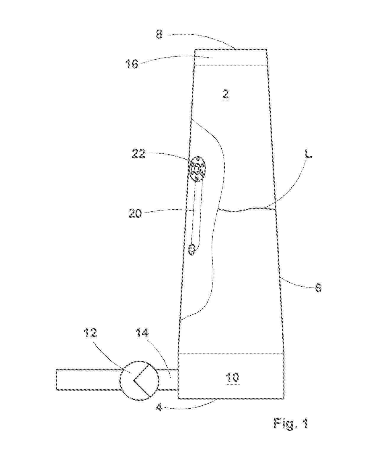
[0047]FIG. 1 illustrates in a relatively large scale a drop leg or a storage tower, from now on called more generally a vessel 2, including a bottom wall 4, a more or less upright side wall or walls 6 and a top cover 8. Further the vessel 2 has, above the bottom wall, a bottom part 10 to which a pump 12 is coupled for discharging a fluid from the vessel 2. The pump 12, with the help of the vessel outlet 14, may be positioned either to the side wall 6 or to the bottom wall 4 of the vessel. Further, the vessel 2 has a top part 16 via which the fluid is normally introduced in the vessel 2. However, it has to be understood that in prior art there are vessels into which the fluid enters via inlet device (or means) arranged through the bottom wall 4 or the side wall 6 of the vessel 2.

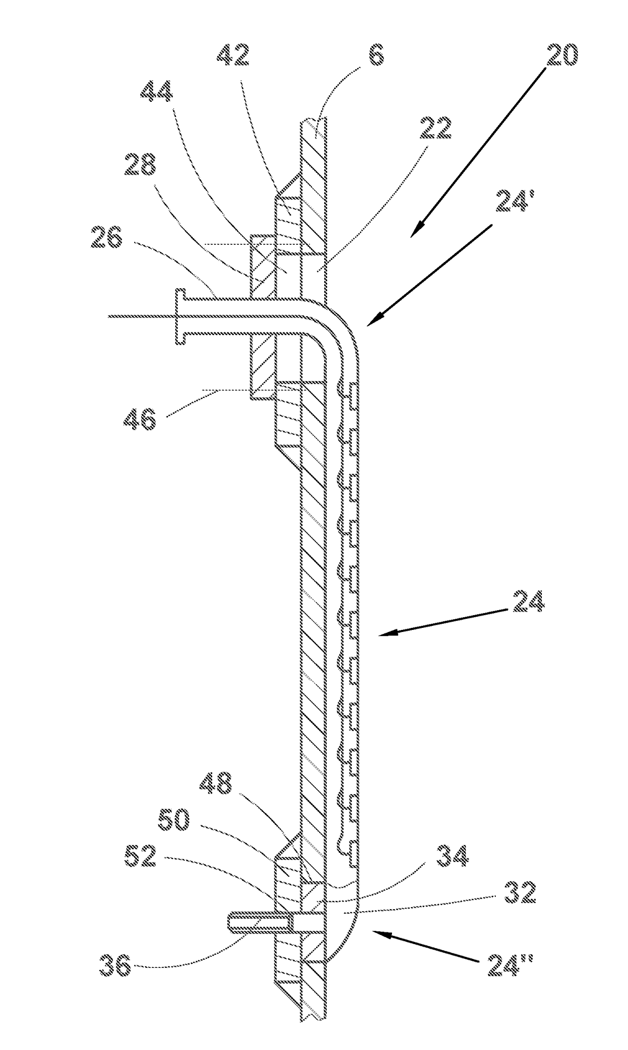
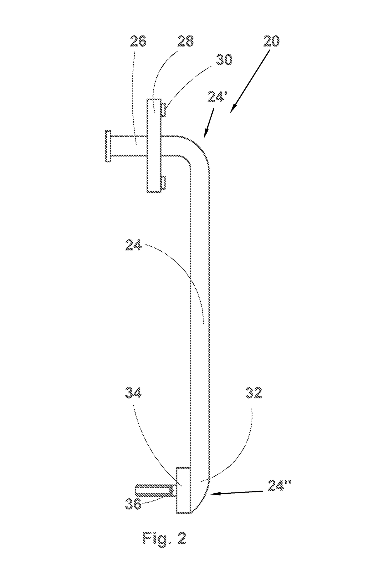
[0048]The vessel 2 of FIG. 1 further includes, in accordance with a first preferred application of the present invention, the apparatus 20 for monitoring the surface level of a fluid in the vessel 2, i.e. a s...


PUM


Abstract

A method of installing a probe for monitoring a surface level of a fluid in a vessel inside the vessel from outside the vessel, the method includes providing a vessel side wall with a first opening, providing the vessel side wall with a second opening, passing the second end of the probe, a second device for fastening the probe and a detection unit of the probe through the first opening and inside the vessel, orienting the second end of the probe towards the second opening, attaching the second end of the probe to the side wall of the vessel at the second opening, and fastening the first end of the probe to the side wall of the vessel at the first opening.

Description

CROSS-REFERENCE TO RELATED APPLICATIONS[0001]This application is a U.S. National State Application of International Application No. PCT / EP2014 / 067303, filed Aug. 13, 2014, which claims priority to European Application No. 13182024.3, filed Aug. 28, 2013, the contents of which is hereby incorporated herein by reference.BACKGROUND[0002]Field of Invention[0003]The present invention relates to a probe for monitoring the surface level of a fluid in a vessel, and to a method of installing the apparatus in the vessel. The apparatus of the present invention is applicable in all such vessels, containers, tanks, drop legs, blow tanks, reactors, etc. where information on the surface level of the fluid present in the vessel is needed for controlling the application. An example is a vessel from which the fluid is about to be pumped further such that the surface level in the vessel is maintained within certain limits, whereby the operation of the feed and / or discharge pump have / has to be adjusted...

Claims


Application Information

Patent Timeline
Patent Type & Authority Patents(United States)
IPC IPC(8): G01F23/24G01F23/26G01F23/14
CPCG01F23/242G01F23/14G01F23/24G01F23/248G01F23/26G01F23/268
Inventor HEINONEN, JUSSIKVICK, PASILEHTONEN, ANSSINYMAN, SEPPOVESALA, REIJOVIKMAN, VESA
Owner SULZER MANAGEMENT AG
Why Eureka
Try Eureka