Harvest sweeper attachment system

a technology of attachment system and sweeper, which is applied in the field of agricultural implements, can solve the problems of affecting the efficiency of collection, complexity and/or durability, and achieve the effects of minimizing the potential for nuts to escape propulsion, convenient installation and removal, and effective operation

Active Publication Date: 2016-07-28
WING SWEEP LLC
View PDF12 Cites 1 Cited by
  • Summary
  • Abstract
  • Description
  • Claims
  • Application Information

AI Technical Summary

Benefits of technology

[0015]An advantage of the present invention is that it provides an accessory to a wide variety of harvesting machines which is easily installable and removable, and thus permits operation on a variety of machines and locations during the harvest season.
[0016]Yet another advantage of the present invention is that the angle of mounting, both of the sweep units themselves and of the rake subassemblies in each unit, works to optimize propulsion of the objects / nuts inward toward the collection scoop of the harvester upon which the invention is mounted.
[0017]A further advantage of the present invention is that the riser plates mounted on each tine bar minimize the potential for nuts escaping propulsion by hopping over the rake.
[0018]Still another advantage of the harvest sweeper system of the present invention is that it will operate effectively with both standalone and tractor driven harvesting machines.
[0019]These and other objects and advantages of the present invention will become clear to those skilled in the art in view of the description of the best presently known mode of carrying out the invention and the industrial applicability of the preferred embodiment as described herein and as illustrated in the several figures of the drawings.

Problems solved by technology

However, all have had drawbacks in efficiency of collection, complexity and / or durability.

Method used


Image

  • Harvest sweeper attachment system
  • Harvest sweeper attachment system
  • Harvest sweeper attachment system

Examples


Embodiment Construction

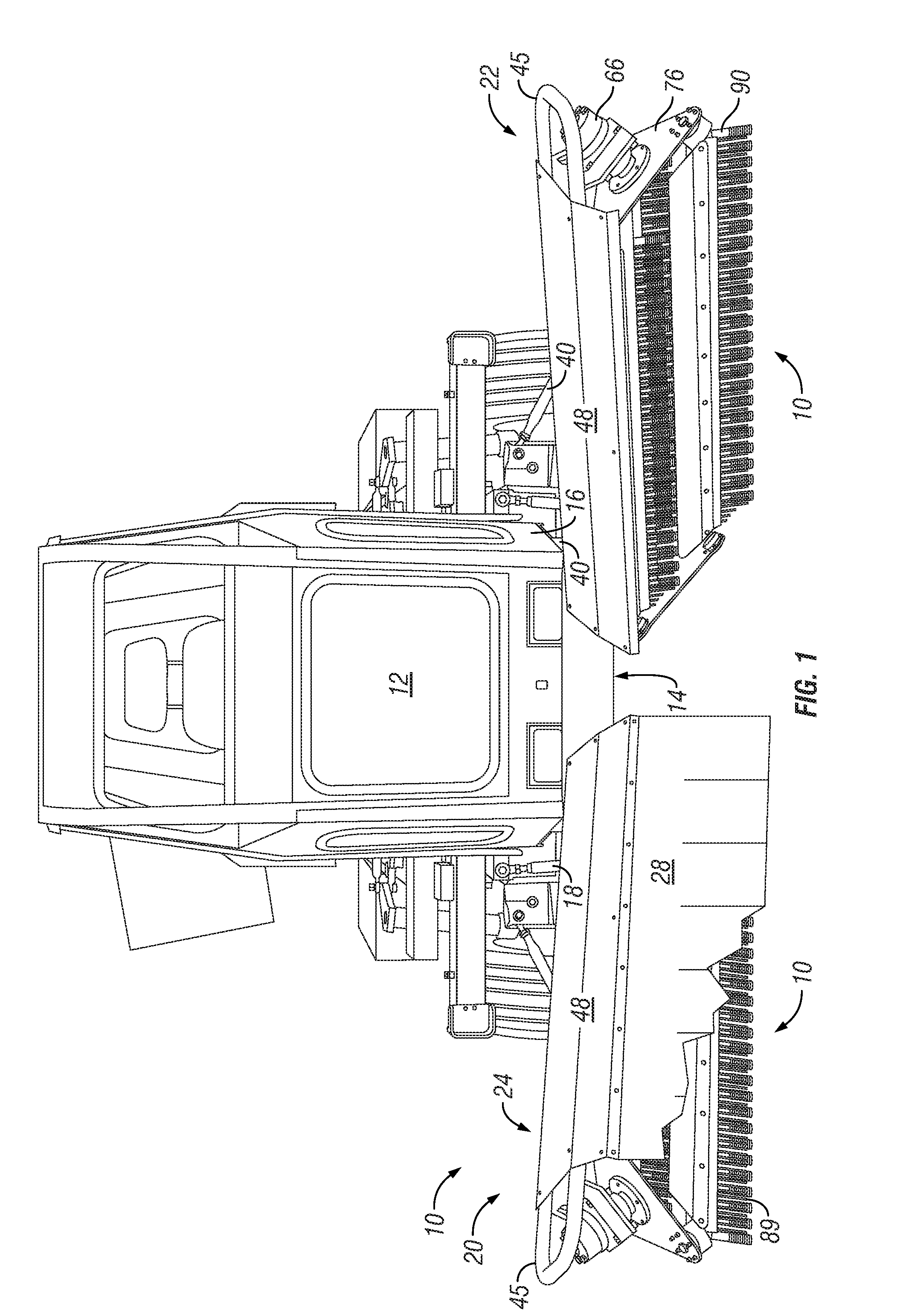
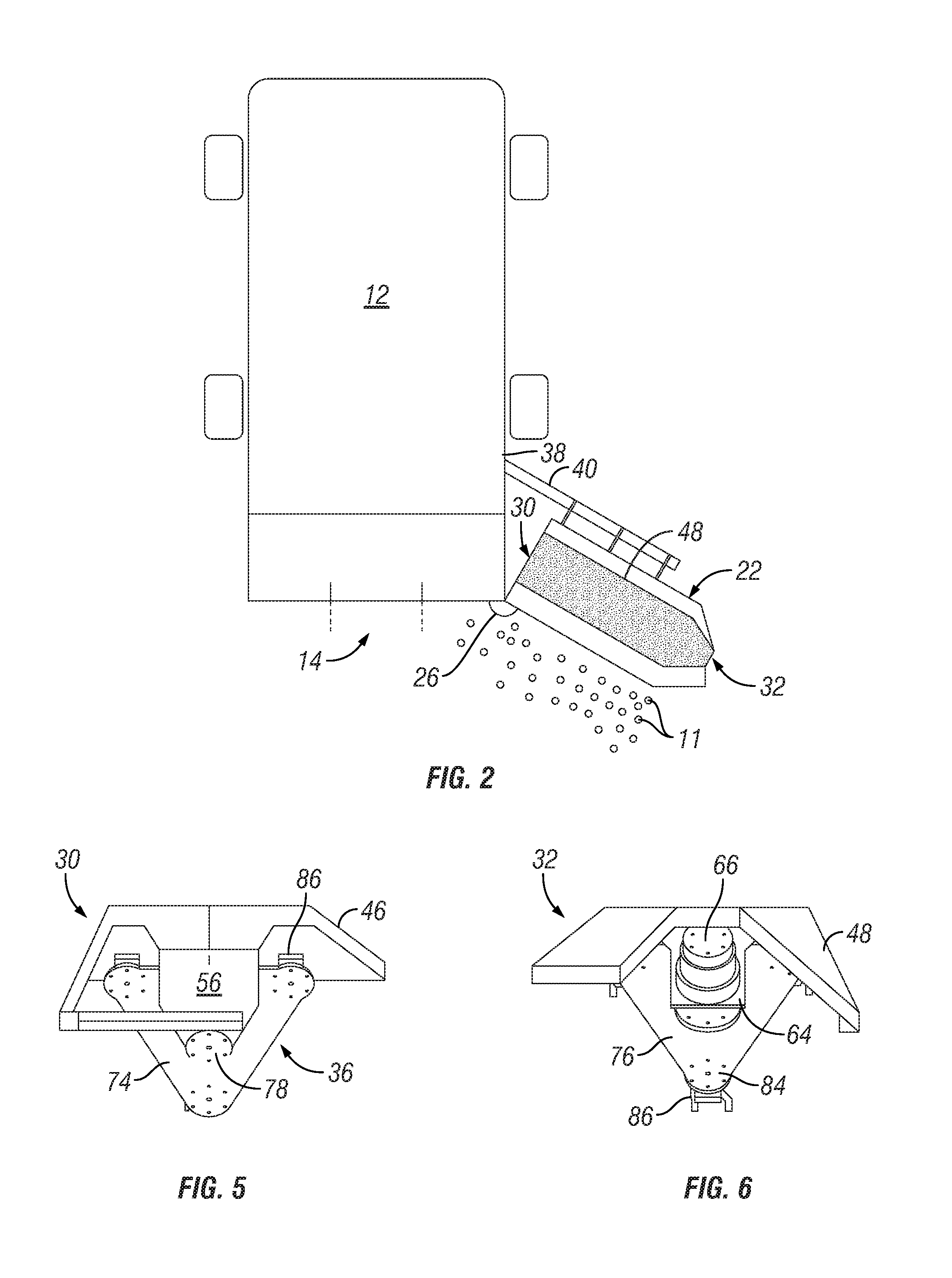
[0027]The present invention is a harvesting sweeper 10 implement particularly adapted for directing and concentrating loose objects 11, such as nuts. The harvesting sweeper 10 is an add-on attachment adapted to be used with any of a variety of harvester machines 12 adapted to actually pick up and process or store the objects 11 directed to them by the sweeper 10.

[0028]A typical nut harvester machine 12, equipped with the inventive sweeper system 10, is shown in a perspective view of FIG. 1. The harvester machine 12 is shown to have, as relevant components for the purposes of the invention: a collection scoop / aperture 14; a harvester frame 16; and hydraulic connectors 18. Other features of the harvester machine 12 are not directly interacting with the inventive sweeper 10 and are thus not specifically identified.

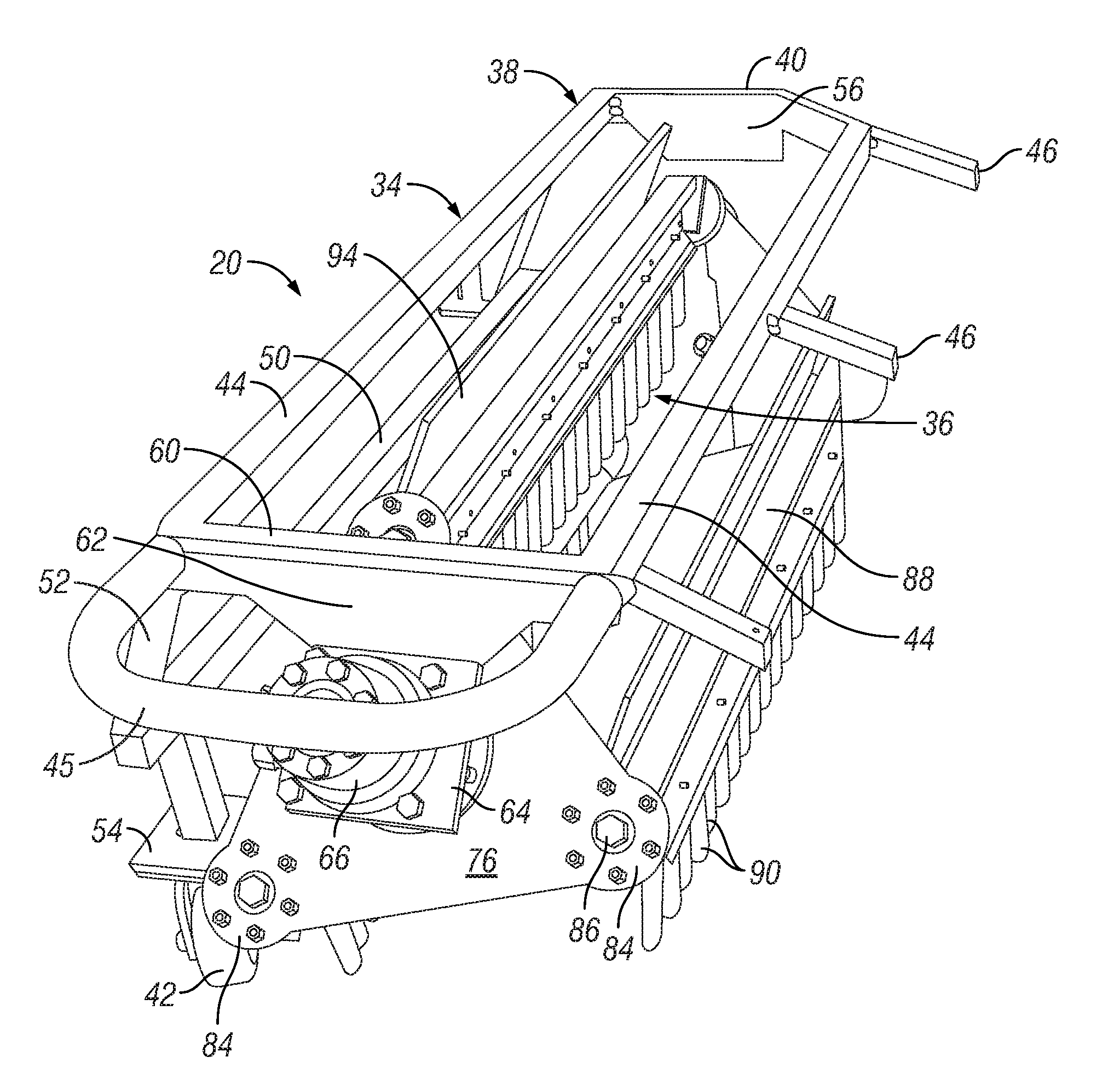
[0029]As shown in FIG. 1 the harvest sweeper system 10 includes two separate but symmetrical sweep head units 20, being a left sweep head 22 and a right sweep head 24 (all co...


PUM


Abstract

A harvest sweeper attachment system (10) is provided for attaching to a harvester machine (12) having a collection aperture (14), for use in propelling desired objects (11), such as nuts, toward the collection aperture (14). The system (10) preferably has two sweep units (20) mounted on each side of the harvester machine (12) at a forward angle, each including a rotating rake subassembly assembly (34). The rake subassembly (34) is characterized by having three axially spaced freely rotating tine bars (88), each having a depending array of tines (90), mounted between a proximal rake plate (74) and a distal rake plate (76). The proximal and distal rake plates (74, 76) are mounted at about a forty-five degree angle such that the rake subassembly (34) has an offset parallelogram aspect.

Description

[0001]This is a non-provisional application, claiming priority from U.S. provisional application No. 62 / 107,902 by the same inventors, filed 26 Jan. 2015.TECHNICAL FIELD[0002]The present invention relates generally to agricultural implements and particularly to harvesting units adapted for harvesting loose crops, such as nuts, from ground surfaces.BACKGROUND ART[0003]Like nearly all other areas of knowledge and commerce, the field of agriculture is subject to continual improvements in techniques and related equipment. This is certainly the case in harvesting implements, where the scythe, rake and pitchfork have gradually given way to increasingly automated methods of picking up and collecting crop elements.[0004]One are of harvesting relates to concentrating the desired crop objects into convenient locations in order to facilitate collection in another step. By concentrating the desired objects, more compact collection equipment may be utilized, with a consequent savings in energy, ...

Claims


Application Information

Patent Timeline
Patent Type & Authority Applications(United States)
IPC IPC(8): A01D51/00A01D57/12
CPCA01D57/12A01D51/002
Inventor GILBERT, MARK E.DIXON, THOMAS VAN
Owner WING SWEEP LLC
Why Eureka
Try Eureka