King pin lock

a king pin and lock technology, applied in the field of king pin locks, can solve the problems of large theft of unattended trailers, unattended left unattended, and substantial annual loss suffered by shippers and insurance companies due to highjacking of trailers

Inactive Publication Date: 2005-11-03
PAQUET MARIO PLARRE
View PDF7 Cites 2 Cited by
  • Summary
  • Abstract
  • Description
  • Claims
  • Application Information

AI Technical Summary

Benefits of technology

[0013] Advantages of the present invention include that the proposed king pin lock is lockable to the coupling pin of a vehicle such as a trailer for preventing unauthorised used of the vehicle.
[0016] The proposed king pin lock is also designed so as to reduce the risks of having a tractor attached thereto so as to pull the trailer having the king pin lock mounted on the king pin.
[0017] Yet, still furthermore, the proposed king pin lock is designed so as to be able to withstand normal operational conditions including the presence of surrounding oil, dust and the like with reduced risks of altering the functioning of the king pin lock.
[0018] Also, the proposed king pin lock is designed so as to be easily installable and removable by a user thereof on a conventional king pin of most conventional trailers through a set of quick and ergonomic steps without requiring special tooling or manual dexterity.
[0020] Also, the proposed king pin lock is designed so that the key for operating it may only be retracted from the locking mechanism when the king pin lock is in its locked configuration for reducing the risks of having the king pin lock held by the trailer coupling pin without being locked thereto. This prevents removal of the key from the lock cylinder except when the lock cylinder is in its locked condition, thereby providing a positive, visually detectable way to determine if the king pin lock is locked to the trailer or simply secured thereto. The king pin lock also includes a dead bolt-type mechanism so that it cannot be locked to a coupling pin without a key.
[0021] Yet, still furthermore, the proposed king pin lock is designed so as to be manufacturable using conventional parts and conventional forms of manufacturing so as to provide a king pin lock that will be economically feasible, long-lasting and relatively trouble-free in operation.

Problems solved by technology

There are many occasions wherein trailer are uncoupled from tractors and are left unattended.
In such instances, an unauthorized person with a tractor having a complementary skid plate for the trailer king pin may simply couple to the trailer, connect the air hoses to release the trailer brakes and haul the trailer away.
Hence, the theft of unattended trailers has been a large problem because it is a simple matter to attach a tractor and merely drive away.
The annual lost sustained by shippers and insurance companies due to highjacking of trailers Is indeed very substantial.
Although somewhat useful, most prior art king pin locks suffer from numerous disadvantages and, hence, are not entirely satisfactory.
For example, some prior art king pin locks are simply not strong enough to resist the heavy blow from a sledge or the like without being broken and thus rendered useless.
Other prior art king pin locks, while being able to sustain a relatively heavy blow from a sledge in normal temperature conditions, may be unable to resist such a blow when subjected to temperature stresses.
Furthermore, some prior art king pin locks are unable to resist to other types of stresses such as chemical stresses or combinations of thermal and chemical stresses.
In prior art king pin locks using a lock cylinder, the latter is exposed so that it could be easily tampered with.
Some prior art king pin locks require relatively numerous costly parts or expenses to manufacture.
Some prior art king pin locks also contain parts which are particularly susceptible to wear and / or to being rendered inefficient In conventional operational conditions.
Still furthermore, some prior art king pin locks are difficult to install and remove by the user.

Method used


Image

  • King pin lock
  • King pin lock
  • King pin lock

Examples


Embodiment Construction

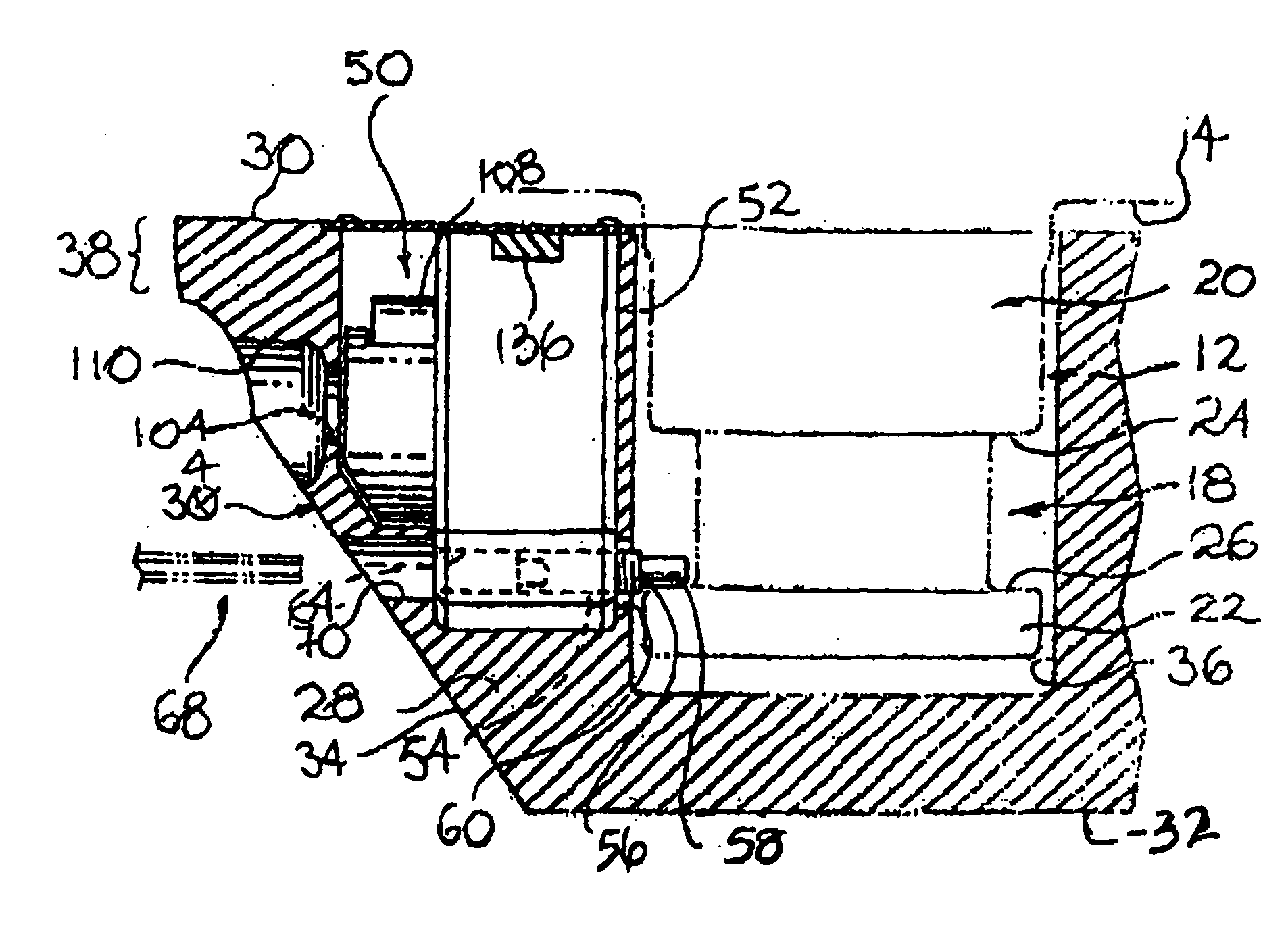
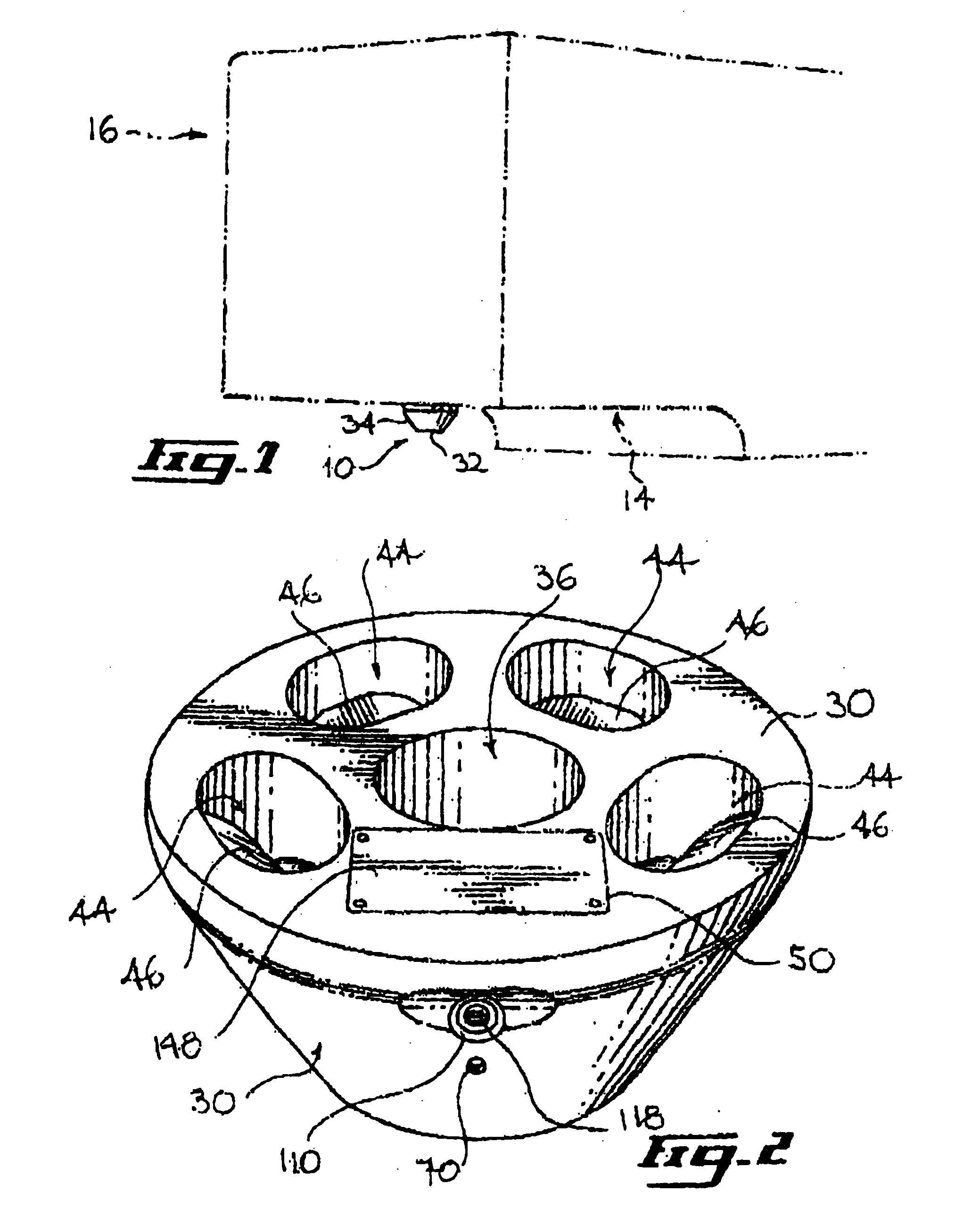
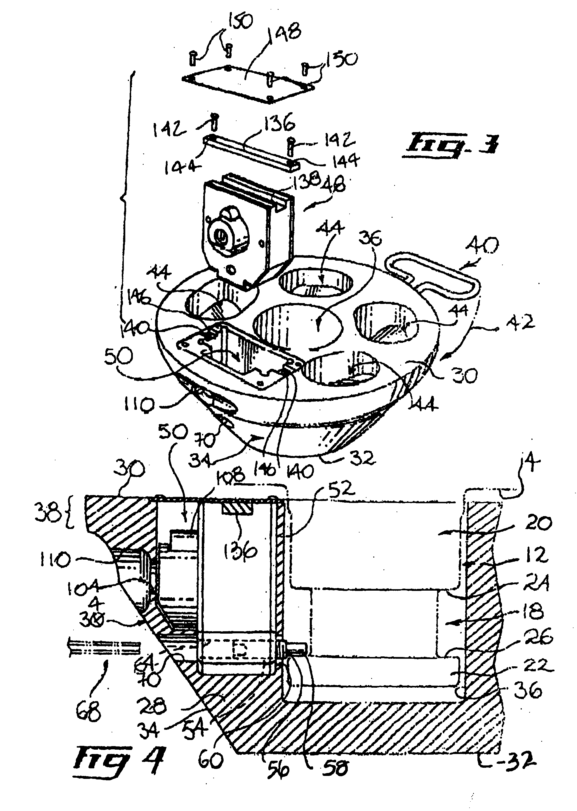
[0032] Referring to FIG. 1, there is shown a king pin lock in accordance with an embodiment of the present invention, generally designated by the reference numeral 10. The king pin lock is shown operationally mounted over a conventional king pin 12 (shown in FIG. 4) extending downwardly from an undersurface 14 of a conventional trailer or semi-trailer 16 adjacent a front end thereof. Typically, although by no means exclusively, the king pin 12 extends from a bearing pad of the trailer or semi-trailer 16.

[0033] The king pin lock 10 is intended to prevent engagement by an unauthorised tractor (not shown) of the king pin 12 so as to prevent the trailer 16 from being hitched to the unauthorised tractor and stolen. It should, however, be understood that the king pin lock 10 could be used in other contexts such as for preventing the theft of other types of vehicles or in other theft prevention setting without departing from the scope of the present invention.

[0034] The conventional king...


PUM


Abstract

A king pin lock mountable over a king pin of a trailer so as to selectively prevent engagement of the king pin, the king pin being provided with an annular recess defining a pair of locking shoulders. The king pin lock includes a king pin lock housing defining a housing upper surface, an opposed housing bottom surface and a housing peripheral surface extending therebetween. The king pin lock housing is provided with a king pin receiving recess for slidably and substantially fittingly receiving the king pin. The king pin lock also includes a housing locking assembly for releasably locking the king pin in the king pin receiving aperture. The housing locking assembly includes a locking component for selectively lockingly engaging the king pin annular recess so as to abut against the king pin lower shoulder and prevent retraction of the king pin from the king pin receiving aperture. An access limiting assembly is provided for selectively limiting access to the locking component so as to prevent illegal retraction of the locking component from the king pin recess.

Description

FIELD OF THE INVENTION [0001] The present Invention relates to the general field of theft prevention devices and is particularly concerned with a king pin lock. BACKGROUND OF THE INVENTION [0002] Tractor-trailer combinations are commonly used for the transportation of freight. The conventional tractor-trailer hitch or coupling structure has been standardised so that practically any tractor can be coupled to any trailer. Conventional tractor-trailer trucking rigs typically include a cylindrical king pin extending downwardly from the bottom surface of the trailer adjacent a front edge thereof. The king pin is provided with an exterior circumferential groove. [0003] The conventional tractor-trailer trucking rig also includes a complementary skid plate receptacle or fifth wheel mounted to the rear of the tractor. The fifth wheel is provided with a skid plate having an opening in which the king pin of the trailer is carried. [0004] The annular groove of the king pin is typically engaged ...

Claims


Application Information

Patent Timeline
Patent Type & Authority Applications(United States)
IPC IPC(8): B62D53/06B62D53/08
CPCB62D53/085
Inventor PAQUET, MARIO PLARRE
Owner PAQUET MARIO PLARRE
Why Eureka
Try Eureka