Power system

Active Publication Date: 2020-09-17
HONDA MOTOR CO LTD
View PDF0 Cites 2 Cited by
  • Summary
  • Abstract
  • Description
  • Claims
  • Application Information

AI Technical Summary

Benefits of technology

[0008]A power system according to an aspect of the disclosure (e.g., the power system 1 described afterwards) includes: a high voltage circuit (the first power circuit 2 described afterwards) having a high voltage power source (e.g., the first battery B1 described afterwards); a low voltage circuit (the second power circuit 3 described afterwards) having a low voltage power source (e.g., the second battery B2 described afterwards), wherein a used voltage range of the low voltage power source with respect to a closed circuit voltage overlaps with the high voltage power source, and a static voltage of the low voltage power source is lower than the high voltage power source; a voltage converter (e.g., the voltage converter 5 described afterwards), converting a voltage between the high voltage circuit and the low voltage circuit; a power converter (e.g., the power converter 43 described afterwards), converting power between the high voltage circuit and a driving motor (e.g., the driving motor M described afterwards); a passing current obtaining section (e.g., the current sensor 33 described afterwards), obtaining a passing current which is a current flowing through the voltage converter; a passing current control section (e.g., the passing power control part 73a described afterwards), operating the voltage converter so that the passing current becomes a target current; and a failure determining section (e.g., the failure determining part 73b described afterwards), determining failure of the voltage converter based on a difference between the passing current and the target current. The failure determining section determines that the voltage converter fails in a case where the difference is greater than a predetermined value and the passing current flows from a side of the high voltage circuit to a side of the low voltage circuit.
[0009]A power system according to another aspect of the disclosure (e.g., the power system 1 described afterwards) includes: a high voltage circuit (the first power circuit 2 described afterwards) having a high voltage power source (e.g., the first battery B1 described afterwards); a low voltage circuit (the second power circuit 3 described afterwards) having a low voltage power source (e.g., the s

Problems solved by technology

For this reason, if the failure of the voltage converter is determined simply based on the difference between the passing current and the ta

Method used


Image

  • Power system
  • Power system
  • Power system

Examples


Embodiment Construction

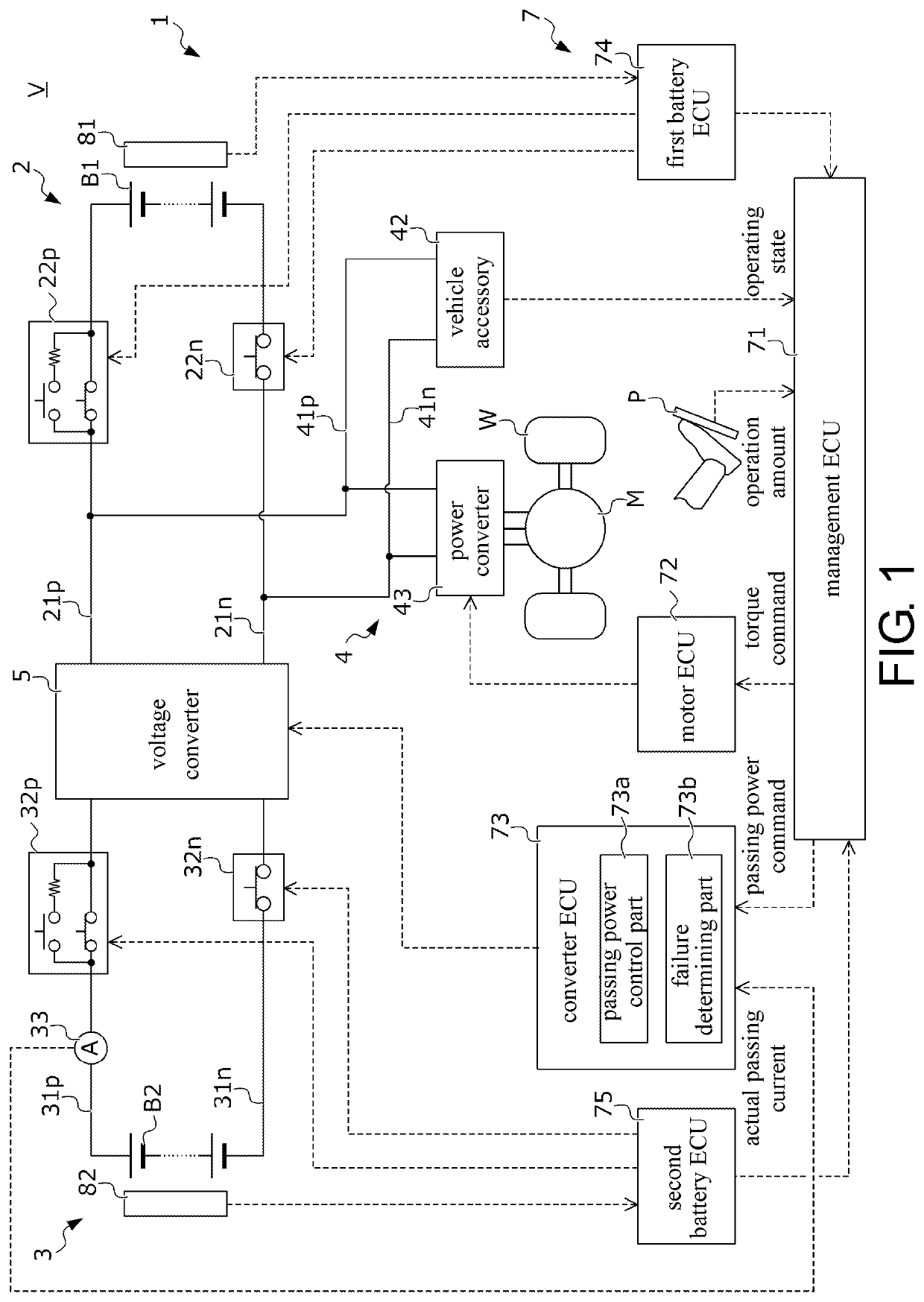
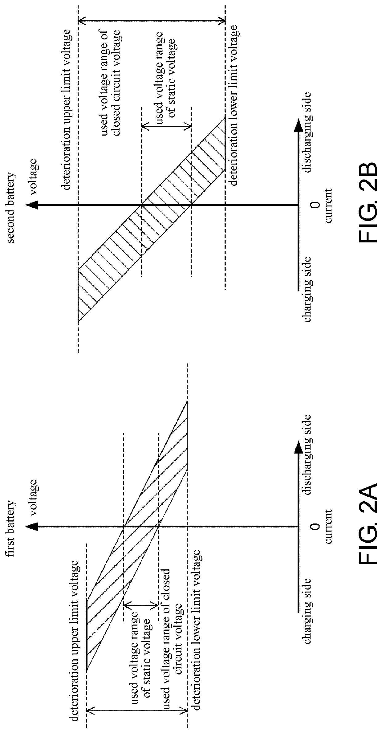
[0020](1) In the power system of the disclosure, the high voltage circuit and the low voltage circuit are connected by the voltage converter. The high voltage circuit has the high voltage power source. The low voltage circuit has the low voltage power source. The used voltage range of the low voltage power source with respect to the closed circuit voltage overlaps with the high voltage power source, and the static voltage of the low voltage power source is lower than the high voltage power source. The passing current control section operates the voltage converter so that the passing current flowing through the voltage converter becomes the target current. When the voltage converter in such power system fails, the passing current that is of an unintentional magnitude may flow from the side of the high voltage circuit to the side of the low voltage circuit. Therefore, the failure determining section determines that the voltage converter fails in the case where the difference between t...


PUM


Abstract

A power system includes: a first power circuit having a first battery; a second power circuit having a second battery, wherein a used voltage range of the second battery with respect to a closed circuit voltage overlaps with the first battery, and a static voltage of the second battery is lower than the first battery; a voltage converter, converting a voltage between the first and the second power circuit; a power converter, converting power between the first power circuit and a driving motor; a current sensor; a passing current control section, operating the voltage converter so that the passing current becomes a target current; and a failure determining section. The failure determining section determines the voltage converter fails in a case where the difference is greater than a threshold and the passing current flows from the side of the first power circuit to the side of the second power circuit.

Description

CROSS-REFERENCE TO RELATED APPLICATION[0001]This application claims the priority of patent Japan application serial no. 2019-046999, filed on Mar. 14, 2019. The entirety of the above-mentioned patent application is hereby incorporated by reference herein and made a part of this specification.BACKGROUNDTechnical Field[0002]The disclosure relates to a power system. More specifically, the disclosure relates to a power system including a high voltage power source and a low voltage power source whose used voltage ranges with respect to closed circuit voltages overlap.Description of Related Art[0003]In recent years, electric vehicles such as electric conveying machines including driving motors as power generating source, hybrid vehicles including driving motors and internal combustion engines as power generating source, etc., are undergoing progressive development. In such an electric vehicle, a power apparatus such as a power storage device (battery, capacitor, etc.), a fuel cell, etc., ...

Claims


Application Information

Patent Timeline
IPC IPC(8): H02M3/335H02J1/10
CPCH02M3/33507H02M2001/0009H02J1/106B60L3/0023H02M3/1584H02M1/32H02J7/342H02J7/007188H02J7/005H02J2310/48H02M1/0009
Inventor OGUMA, HIROKAZUOIWA, HISAYA
Owner HONDA MOTOR CO LTD
Why Eureka
Try Eureka