Advanced stabilizing system for deep drilling

a stabilizing system and deep drilling technology, applied in the direction of drilling rods, drilling pipes, drilling casings, etc., can solve the problems of affecting the stability of the drilling shaft, affecting the drilling speed of the drill, and causing severe drag

a stabilizing system and deep drilling technology, applied in the direction of drilling rods, drilling pipes, drilling casings, etc., can solve the problems of affecting the stability of the drilling shaft, affecting the drilling speed of the drill, and causing severe drag

US20220251910A1Pending Publication Date: 2022-08-11ADNOC

Image

  • Advanced stabilizing system for deep drilling
  • Advanced stabilizing system for deep drilling
  • Advanced stabilizing system for deep drilling

Examples


Embodiment Construction

[0044]In the following, the invention as further described exemplarily with references to the enclosed figures. Therein, similar components are provided with same reference signs.

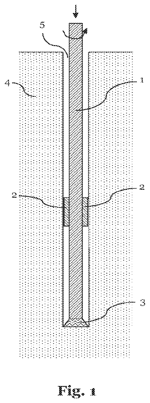
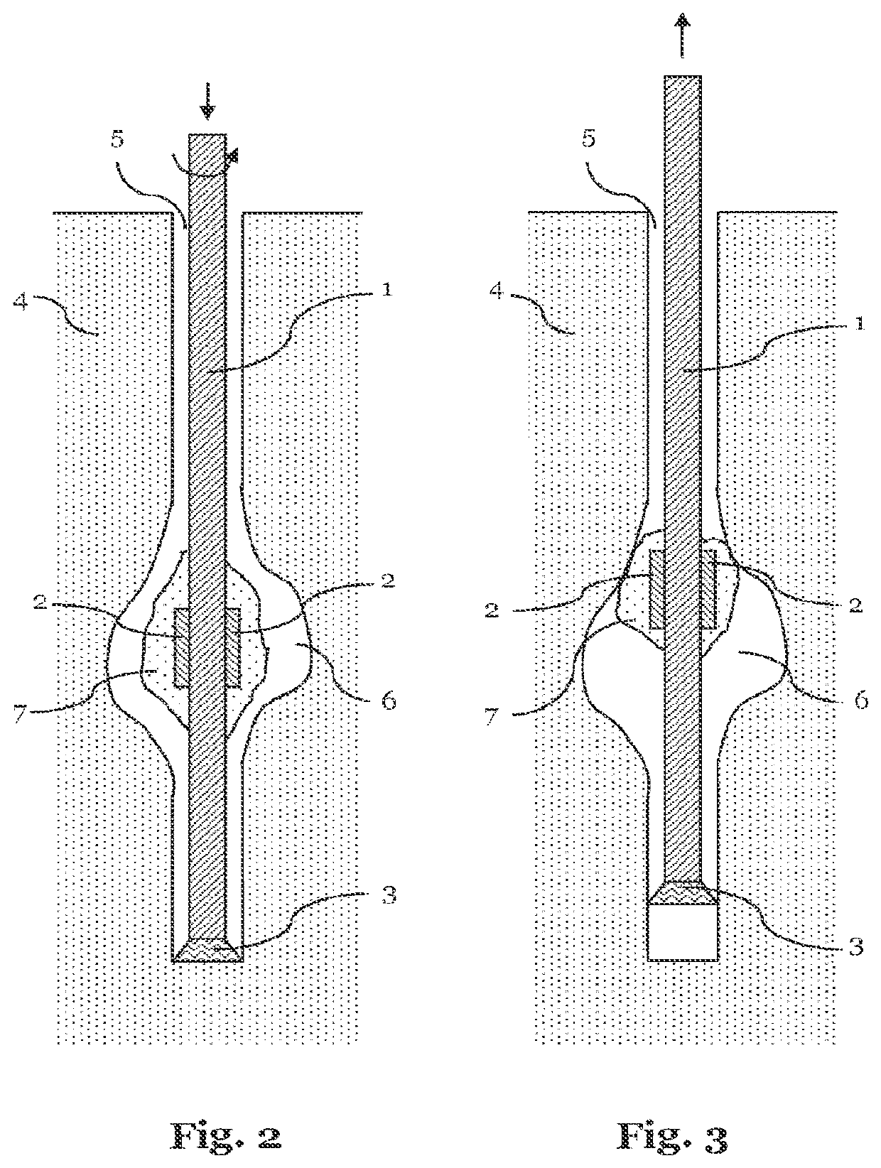
[0045]FIGS. 1-3 illustrate schematically a drilling system in different configurations.

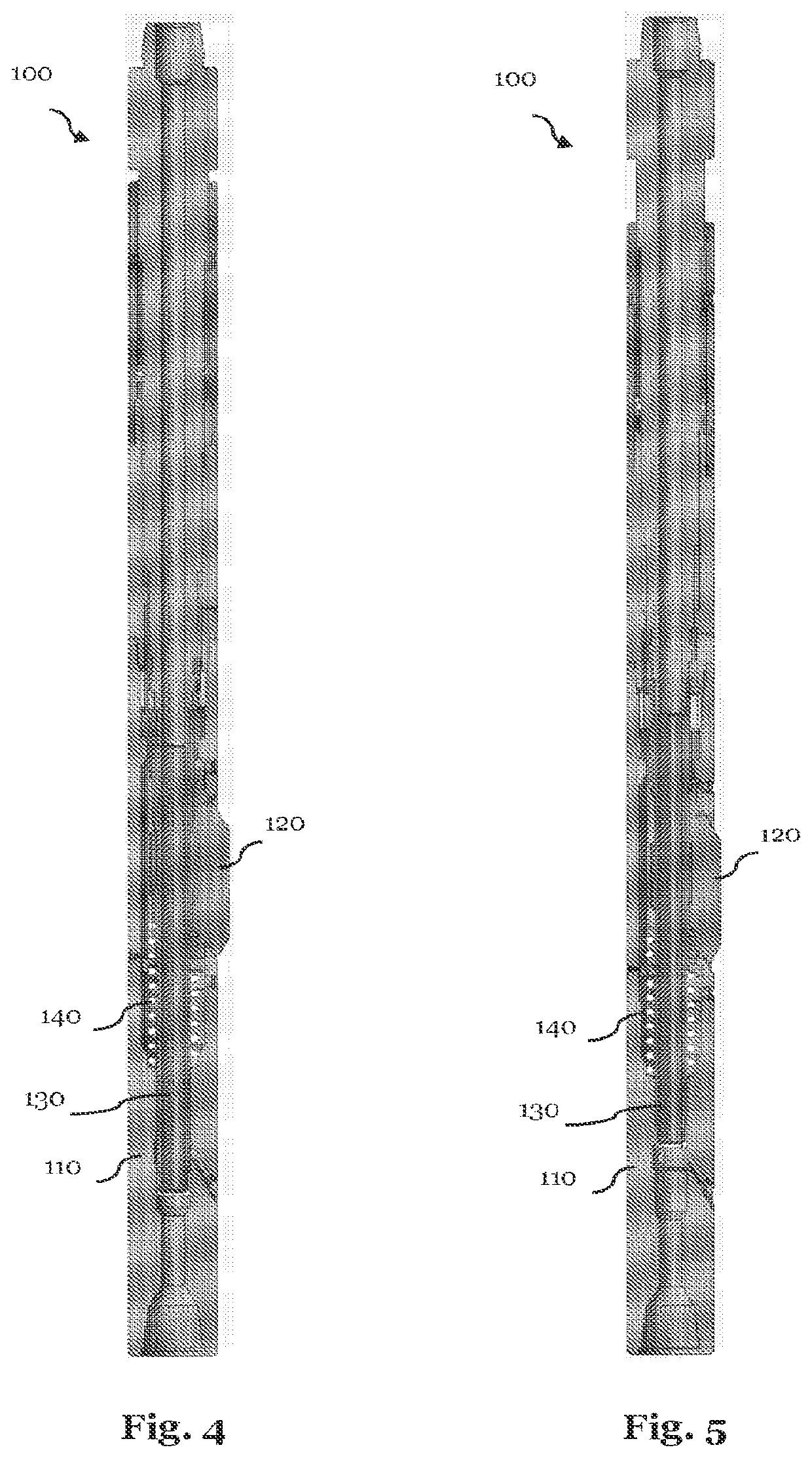
[0046]FIG. 4 illustrates a cross section of a stabilizing system according to a preferred embodiment of the present invention.

[0047]FIG. 5 illustrates the stabilizing system of the embodiment illustrated in FIG. 4 in a different configuration.

[0048]FIG. 6 illustrates particular details of the stabilizing system of FIG. 4.

[0049]FIG. 7 illustrates particular details of the stabilizing system of FIG. 5.

[0050]FIGS. 4 and 5 illustrates a stabilizing system 100 according to an embodiment of the present invention. The stabilizing system 100 is thereby adapted to be connected to drill pipes at each end thereof via respective drill pipe linkages. In the configuration illustrated in FIG. 4, the stabilizing system 100 is in a state ...


PUM


Abstract

The present invention relates to a stabilizing system adapted to be used in a deep drilling system. The stabilizing system comprises a longitudinal housing and a spring, preferably a helical spring, arranged inside the housing. Thereby, the stabilizing system is contracted and the spring is compressed along the longitudinal axis of the stabilizing system when an external load is applied in longitudinal direction onto the stabilizing system. The transversal diameter of the stabilizing system increases when the stabilizing system is contracted. Further, the transversal diameter of the stabilizing system decreases when the stabilizing system expands along the longitudinal axis.

Description

RELATED APPLICATION DATA[0001]This application is a continuation of U.S. patent application Ser. No. 17 / 252,078, filed Dec. 14, 2020, which is a national phase of International Patent Application No. PCT / IB2018 / 054235, filed Jun. 12, 2018, each of which is incorporated herein by reference.FIELD OF THE INVENTION[0002]The present invention relates to a deep drilling system, and in particular to a stabilizing system to be used in such a deep drilling system, and a method for drilling a hole utilizing such a deep drilling system.TECHNICAL BACKGROUND[0003]In a deep drilling system, a drill bit is typically connected via several drill pipes, forming a drill string, to a drilling motor. Such a setup is also generally illustrated in FIG. 1. The drilling motor, provided on the earth's surface, applies drilling forces (the longitudinal and rotational forces as illustrated by arrows in FIG. 1) onto the drill string 1 such that the drill bit 3 advances further into the ground 4, thereby creatin...

Claims


Application Information

Patent Timeline
11 Aug 2022
Publication
US20220251910A1
IPC
E21B17/10
CPC
E21B17/1078; E21B17/1014; E21B17/1021
Inventors
AL AMERI, FAHED SALEM SALEH AWADH; AL AWADHI, FARHAAD KHALED SAEED MOHAMED