Key structure

a key structure and key technology, applied in the field of key structures, can solve the problems of inability to evenly coat the glue material, excess glue material may overflow, drawbacks, etc., and achieve the effect of not affecting the tactile feel and the operation of the key structur

Active Publication Date: 2022-09-15
PRIMAX ELECTRONICS LTD
View PDF4 Cites 0 Cited by
  • Summary
  • Abstract
  • Description
  • Claims
  • Application Information

AI Technical Summary

Benefits of technology

[0004]For solving the drawbacks of the conventional technologies, the present invention provides a key structure. A keycap of the key structure includes a flow-guiding bevel surface. When a glue material overflows through a gap between a protective cover and the keycap, the excess portion of the glue material can be retained on the flow-guiding bevel surface of the keycap, and the flow-guiding bevel surface can prevent the glue material from spreading to other regions of the keycap. Since the elastically-stretchable region of the protective cover is not contaminated by the glue material, the tactile feel and the operation of the key structure are not adversely affected.

Problems solved by technology

However, during the process of coating the glue material, some drawbacks occur.
For example, regardless of whether the glue material is coated through a machine or through a manual spraying procedure, the glue material is usually unable to be coated evenly.
Consequently, the excess portion of the glue material may overflow through the gap between the protective cover and the keycap.
In other words, some positions that are not required to be coated with the glue material are contaminated by the glue material.
If the region of the protective cover that is designed to be elastically stretched is contaminated by the glue material and adhesively fixed on the keycap, the upward / downward movement of the keycap is pulled and hindered by the protective cover.

Method used


Image

  • Key structure
  • Key structure
  • Key structure

Examples


Embodiment Construction

[0018]The present invention will now be described more specifically with reference to the following embodiments and accompanying drawings.

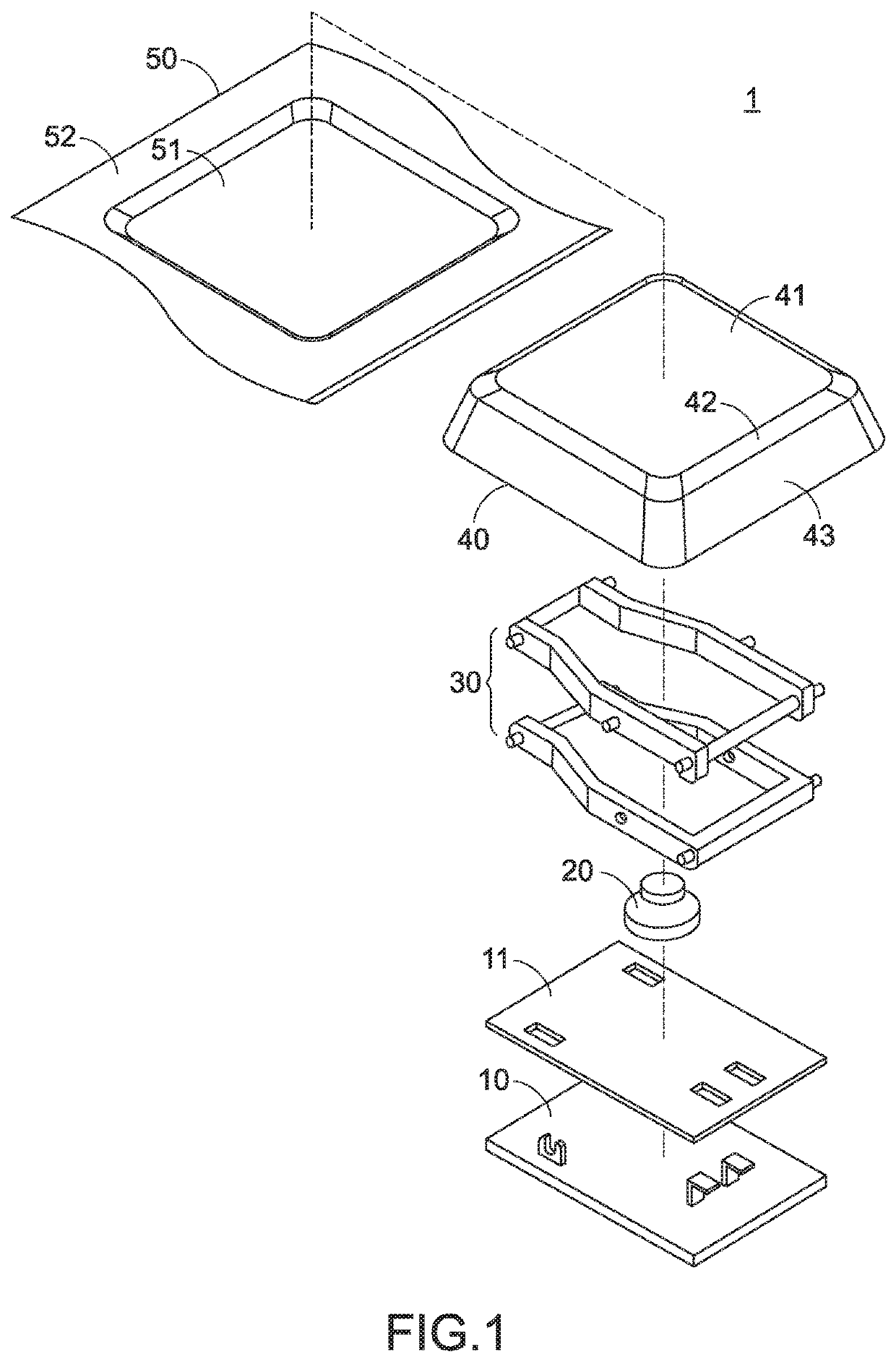
[0019]FIG. 1 is a schematic exploded view illustrating a key structure according to an embodiment of the present invention. As shown in FIG. 1, the key structure 1 comprises a base plate 10, a switch circuit layer 11, an elastic element 20, a supporting element 30, a keycap 40 and a protective cover 50.

[0020]The switch circuit layer 11 is installed on the base plate 10. The switch circuit layer 11 can generate a key signal. The elastic element 20 is installed on the base plate 10 and located over the switch circuit layer 11. The switch circuit layer 11 can be triggered by the elastic element 20. The supporting element 30 is installed on the base plate 10 and arranged around the elastic element 20. The keycap 40 is located over the supporting element 30 and connected with the supporting element 30. As the supporting element 30 is moved, the keycap ...


PUM


Abstract

A key structure includes a protective cover and a keycap. The keycap includes flow-guiding bevel surface. When the protective cover and the keycap are adhered on each other through a glue material, an excess portion of the glue material is retained on the flow-guiding bevel surface. Consequently, the excess portion of the glue material will not spread to other regions.

Description

FIELD OF THE INVENTION[0001]The present invention relates to a key structure, and more particularly to a key structure of a computer keyboard.BACKGROUND OF THE INVENTION[0002]Generally, a keyboard of a computer usually comprises plural keys. For preventing dust or liquid from entering the seams between keys or flowing into the underlying spaces, the keyboard is usually additionally equipped with a layer of soft and elastic protective cover. The protective cover is located over the keycaps of the keys to cover the keycaps in order to block dust or other foreign matters. Moreover, due to the elasticity and the flexibility of the protective cover, the user can smoothly press down the keycaps to trigger key signals. Moreover, for positioning the protective cover on the keycaps, it is necessary to attach a portion of the protective cover on the top surfaces of the keycaps. For example, a glue material is firstly coated on the region between the protective cover and the keycap, and then t...

Claims


Application Information

Patent Timeline
Patent Type & Authority Applications(United States)
IPC IPC(8): H01H13/7065H01H13/14H01H13/704H01H13/04
CPCH01H13/7065H01H13/14H01H13/704H01H13/04H01H2003/127H01H2209/068H01H2203/038
Inventor WU, MING-HANCHEN, YI-WEICHANG, HSIEN-TSAN
Owner PRIMAX ELECTRONICS LTD
Why Eureka
Try Eureka