Motor mounted in a vehicle

a technology for motors and vehicles, applied in the direction of windings, magnetic circuit rotating parts, magnetic circuit shapes/forms/construction, etc., can solve the problems of reducing the magnetic strength of ferrite magnets, affecting the operation efficiency of rotors, and affecting the operation efficiency of ferrite magnets

Inactive Publication Date: 2000-01-04
NIPPON DENSAN CORP
View PDF8 Cites 163 Cited by
  • Summary
  • Abstract
  • Description
  • Claims
  • Application Information

AI Technical Summary

Problems solved by technology

If, as set out above, the end portions of the copper wire and lead wire are tied together and fixed or they are fixed together through the PC plate, there is sometimes a chance that their fixed areas are disconnected due to a vibration resulting from the running of the vehicle.
As a result, the problem arises because of lowered vibration resistance and impact resistance in the vehicle.
This operation is time-co

Method used


Image

  • Motor mounted in a vehicle
  • Motor mounted in a vehicle
  • Motor mounted in a vehicle

Examples


Embodiment Construction

The embodiment of the present invention will be explained below with reference to the accompanying drawings. FIGS. 4 to 20 show one embodiment of the present invention.

The arrangement of a motor mounted in a vehicle will be explained below. The motor 1 is of such a type that it is mounted in the vehicle, for example, it is a 9-pole motor of three-phases, that is, a U-, V- and W-phase.

In a casing 2 of the motor 1, a stator 12 having a plurality of coils 18 and a rotor 4 are provided with an interconnect member 20 arranged above the stator 12 in FIG. 5 and having a structure as will be set out below. An interconnection member 46 is arranged below the stator 12 in FIG. 5 and has a structure as will be set out below. The casing 2 is covered with a cover plate 5 and the interconnection member 20 is connected to a lead wire 36 as will be set out below.

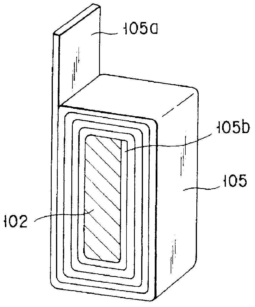
The stator 12 has a ring section 14 and nine projections 16 inwardly extending from the ring section 14. The projection 16 provides a T-sha...


PUM


Abstract

PCT No. PCT/JP96/02929 Sec. 371 Date Jun. 25, 1998 Sec. 102(e) Date Jun. 25, 1998 PCT Filed Oct. 9, 1996 PCT Pub. No. WO97/26700 PCT Pub. Date Jul. 24, 1997A motor mounted in a vehicle having a winding comprising a flat band-like copper wire is provided. The winding is wound on a projection that extends radially inward of a stator. The winding includes a first band-like section that is adapted to be wound on a radially inward portion of the projection of the stator. The winding also includes a connection section that is continuous with one longitudinal end of the first band-like section and extends radially outward along the radial direction of the projection of the stator. The winding further includes a second band-like section that is adapted to be wound on a radially outward portion of the projection of the stator. One longitudinal end of the second band-like section is continuous with the connection section. The first band-like section extends from a radially inward portion of the connection section and the second band-like section extends from a radially outward portion of the connection section. The first and second band-like sections extend from the connection section in opposite directions.

Description

The present invention relates to an electric motor mounted in a vehicle, such as a passenger car or truck.PRIOR ARTIn a vehicle such as a passenger car or truck, various motors are mounted such as a motor mounted on an engine and a motor for driving a wiper.The motor mounted in the vehicle has a cylindrical stator and a rotor rotatably mounted at the central area of the stator in which the rotor is equipped with a permanent magnet and produces a rotational force under a magnetic field created by the stator.In the stator of the motor mounted in the vehicle, use is made, as a structure for forming coils for creating magnetic fields, of cylindrical ring sections arranged coaxially with a rotor and a plurality of projections equidistantly mounted on, and along a circumferential direction of, the cylindrical ring unit and directed at their forward ends toward the rotor side with each projection wound with a winding such as a copper wire. A magnetic field is created by carrying electric c...

Claims


Application Information

Patent Timeline
IPC IPC(8): H02K3/52H02K5/08H02K3/18H02K3/46H02K5/22H02K1/27
CPCH02K1/278H02K3/18H02K3/522H02K5/08H02K5/225H02K2203/09H02K3/04
Inventor KAWAKAMI, TSUKASA
Owner NIPPON DENSAN CORP
Why Eureka
Try Eureka