Braking system for a vehicle

Inactive Publication Date: 2000-02-01
DENSO CORP
View PDF15 Cites 18 Cited by
  • Summary
  • Abstract
  • Description
  • Claims
  • Application Information

AI Technical Summary

Problems solved by technology

However, when the performance of the booster has deteriorated, because it cannot boost the depressing force on the brake pedal as much as when exhibiting its performance fully, a braking force corresponding to the brake pedal operating amount may not be fully obtained.
In cases like this where the large brake pedal operating amount is required, the necessary depressing force to the brake pedal is large and becomes a burden on the driver.
Therefore, for example when the driver is not a physically strong person this burden may be considerable.
Also, in heavy load driving, when the same braking force as in light load driving is expected from the same depressing force to the bra

Method used


Image

  • Braking system for a vehicle
  • Braking system for a vehicle
  • Braking system for a vehicle

Examples


Embodiment Construction

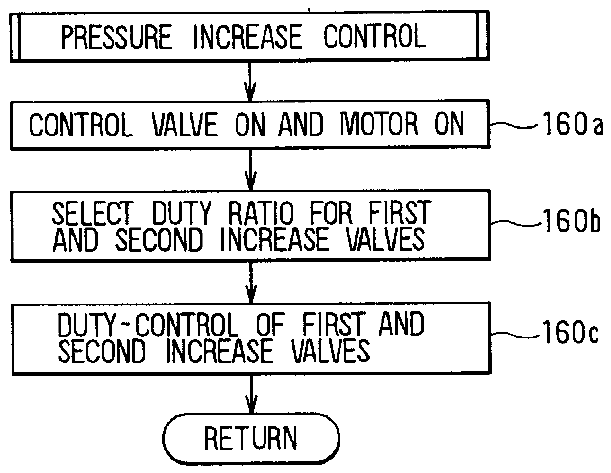
[1] Although in the fourth preferred embodiment described above pressure increase control was carried out by the same processing as in the first preferred embodiment, alternatively pressure increase control may be carried out by the same processing as in the second and third preferred embodiments.

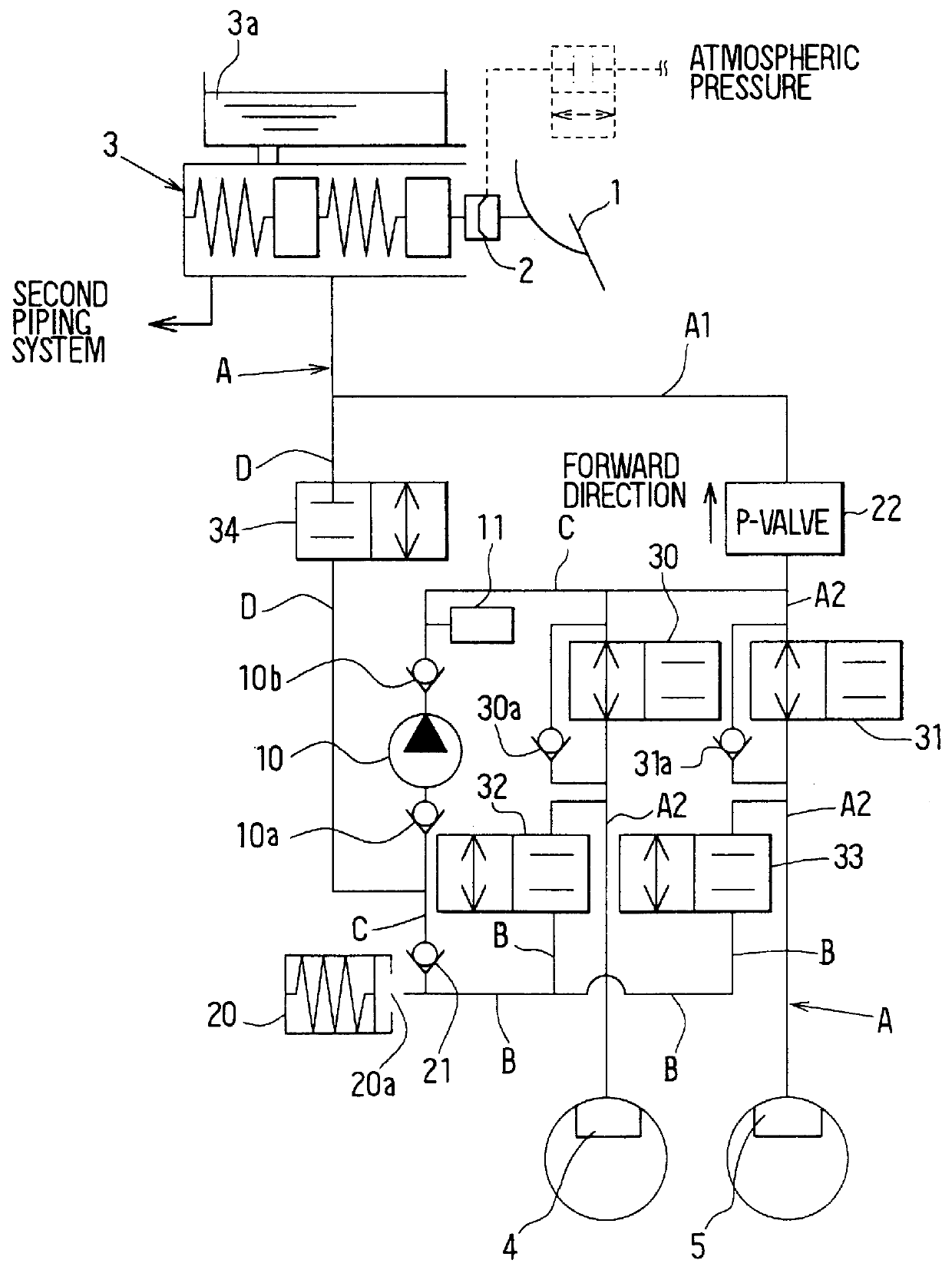
Also, in the first through third preferred embodiments, to prevent the fluid pressure in the conduit A2 from becoming excessive as a result of pressure increase control and prevent damage to the conduit A2, a two-position valve having a differential pressure regulating valve may be disposed in parallel with the proportioning control valve 22.

Also, although as shown in FIG. 1 a proportioning control valve 22 was used to carry out pressure increase control, alternatively this proportional control valve 22 may be dispensed with and just a two-position valve may be used instead. In this case, in place of the control valve 34 this two-position valve may be duty-controlled.

[2] The brake pedal ope...


PUM


Abstract

A vehicle braking system can, for example when the performance of a booster has deteriorated, reduce a brake pedal depressing force required to obtain a sufficient braking force and thereby lighten the burden on the driver. A booster and a master cylinder generate a brake fluid pressure in correspondence with an operation of a brake pedal. Wheel cylinders connected to the master cylinder generate wheel braking forces in wheels of the vehicle. It is determined if a vehicle braking state corresponds to a state of operation of the brake pedal, and when it is determined that the vehicle braking state does not correspond to the brake pedal operation brake fluid pressure in the wheel cylinders is increased with a pump. In this way, it is possible to obtain a predetermined braking force corresponding to the brake pedal operation at all times.

Description

This application is based upon and claims the benefit of priority of the prior Japanese Patent Applications No. H.8-239595 filed Sep. 10, 1996, No. H.9-24146 filed Feb. 6, 1997, and No. H. 9-192933 filed Jul. 17, 1997, the contents of which are incorporated herein by reference.1. Field of the InventionThis invention relates to a braking system for a vehicle, and particularly to a braking system for a vehicle which adjusts a braking force of the vehicle when a high braking force is needed, for example, when the performance of a booster has deteriorated, when the vehicle is traveling downhill or when the vehicle is heavily loaded.2. Description of Related ArtConventionally, a vehicle braking system has been made up of a brake pedal, a booster, a master cylinder, wheel cylinders, and conduits carrying brake fluid. When applying a braking force to the vehicle, a driver depresses the brake pedal. That is, a depressing force applied to the brake pedal is boosted by the booster and transmi...

Claims


Application Information

Patent Timeline
IPC IPC(8): B60T8/88B60T8/94B60T13/68B60T8/48B60T7/04B60T8/44B60T13/66
CPCB60T7/042B60T8/442B60T8/4872B60T8/94B60T13/686B60T8/4827
Inventor SAWADA, MAMORUYONEMURA, SHUICHIABE, YOUICHI
Owner DENSO CORP
Why Eureka
Try Eureka