Optical fiber connector

a technology fiber optic cables, applied in the field of optical fiber connectors, can solve the problems of unsatisfactory use of the connector disclosed in the '634 patent, the latch is prone to entanglement with wires, and the wires become damaged or some portion of the connector becomes damaged

Inactive Publication Date: 2000-02-01
COMMSCOPE TECH LLC
View PDF7 Cites 168 Cited by
  • Summary
  • Abstract
  • Description
  • Claims
  • Application Information

AI Technical Summary

Benefits of technology

Accordingly, it is a general object of the present invention to provide a novel connector which can be used to terminate an optical fiber or conductive member, such as a wir

Problems solved by technology

Tanglement with wires during connection or disconnection of a connector can provide that the wires become damaged or some portion of the connector becomes damaged.
Unfortunately, some SC connectors are comprised of as many as forty-five individual parts.
Because the rearward end of the latch is spaced-apart from the housing, the latch is prone to entanglement with wires upon engagement or disengagement of the connector with the associated receptacle.
Therefore, the connector disclosed in the '634 patent is not ideal for use in environments where there are many loose and/or hanging wires such as which can be found on a patch panel, in a patch enclosure or in an electrical closet.
Additionally

Method used


Image

  • Optical fiber connector
  • Optical fiber connector
  • Optical fiber connector

Examples


Embodiment Construction

While the invention may be susceptible to embodiment in different forms, there is shown in the drawings, and herein will be described in detail, specific embodiments with the understanding that the present disclosure is to be considered an exemplification of the principles of the invention, and is not intended to limit the invention to that as illustrated and described herein.

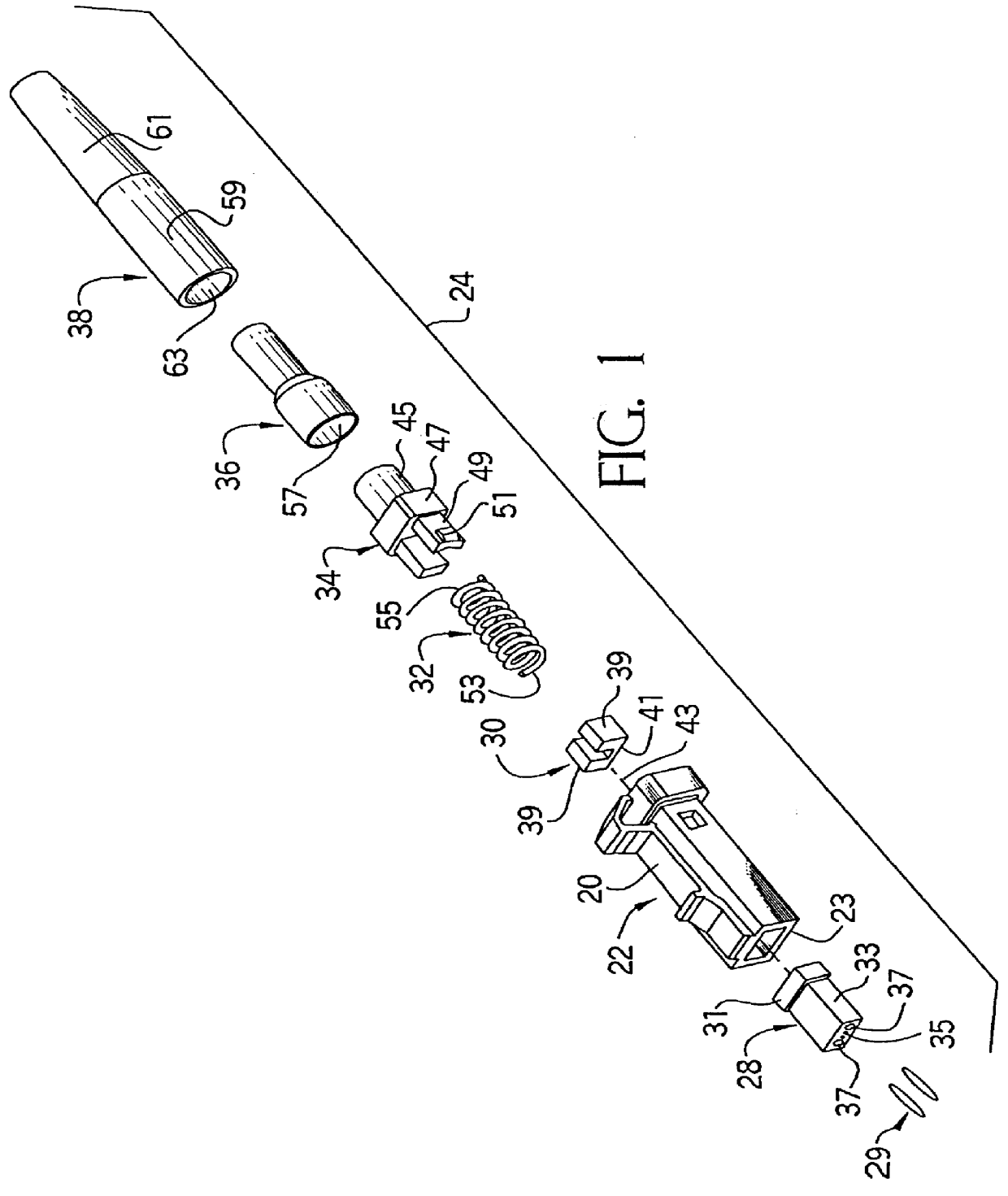
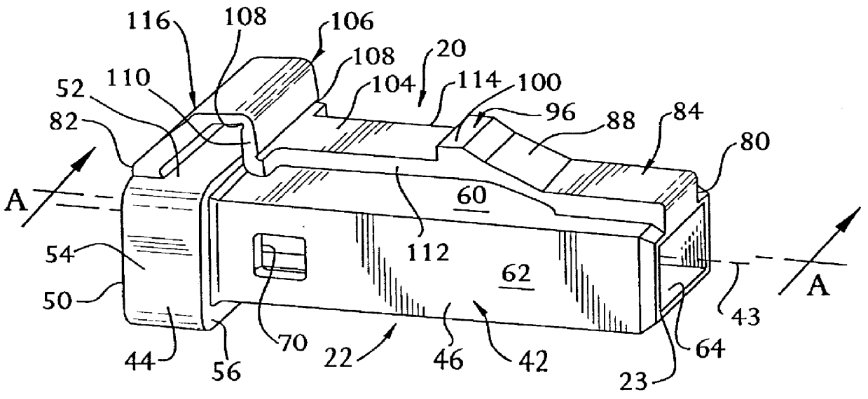
Shown in FIGS. 3, 4, 5, 6 and 7 are plug housings for use in a connector in accordance with the present invention. Specifically, the plug housing 22 shown in FIG. 3 is for use with a novel connector in accordance with a preferred embodiment of the present invention, and the plug housings 22a, 22b 22c and 22d shown in FIGS. 4, 5, 6 and 7, respectively, are for use with connectors in accordance with alternative embodiments of the present invention.

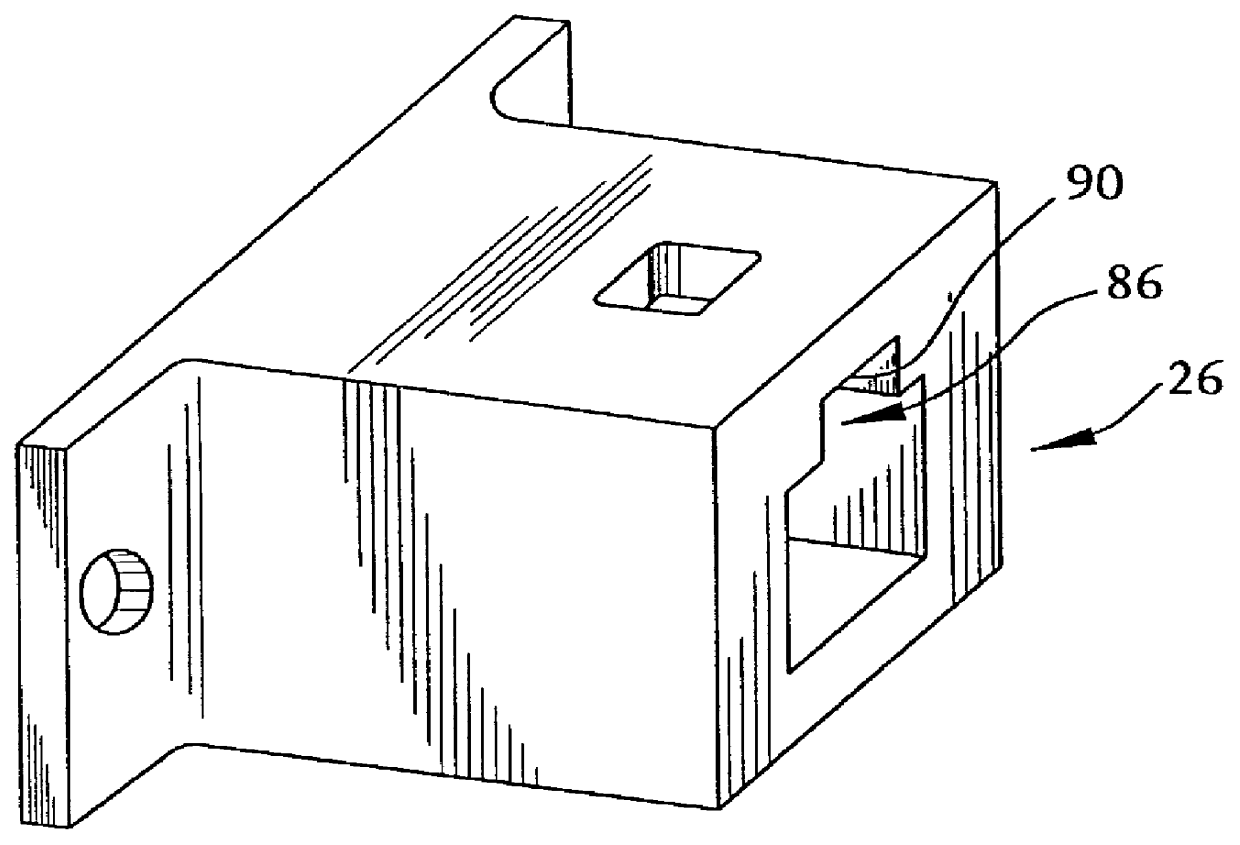
Plug housing 22 is configured to be engaged with an associated receptacle such as the receptacle 26 shown in FIG. 2. In contrast, plug housings 22a, 22b 22c and 22d are...


PUM


Abstract

Disclosed is a connector which can be used to terminate, among other things, an optical fiber. The connector includes a housing, and the housing defines a cavity. The housing has an end configured for insertion into an associated receptacle. On the housing is a latch for securing the housing in the associated receptacle. The latch has a first end and a second end opposite the first end, and each end of the latch is either connected to or simply supported by the housing.

Description

The present invention relates generally to connectors for use with optical fibers, and more specifically relates to a novel connector for use with optical fibers, where the connector includes a latch having each end either connected to a housing or simply supported by the housing.Fiber optic technology presents several advantages which cannot be provided by other technologies. For example, fiber optic communication systems provide immunity from electromagnetic interference (EMI), provide virtually unlimited bandwidth, and provide that data can be quickly transferred over long distances.Typically, connectors are used within optical fiber communication systems. For example, connectors are used to join optical fibers together to form a longer length, or to connect an optical fiber to a device. Generally, an optical fiber connector must provide that the end of one optical fiber becomes axially aligned with the end of another optical fiber. As a result, after the connection is made, all ...

Claims


Application Information

Patent Timeline
IPC IPC(8): G02B6/38
CPCG02B6/3869G02B6/3885G02B6/3887G02B6/3821G02B6/3893G02B6/3888G02B6/38875
Inventor MANNING, RANDY MARSHALLKEVERN, JAMES DAVID
Owner COMMSCOPE TECH LLC
Why Eureka
Try Eureka