Flat panel display screens and systems

a technology for display screens and screens, applied in the field of flat panel display screens and systems, can solve the problems of reduced brightness and contrast, limited viewing angles of displays, bulky in large viewing areas or screen sizes, etc., and achieve the effect of high visibility in sunligh

Inactive Publication Date: 2000-06-13
PIONEER CORP
View PDF8 Cites 43 Cited by
  • Summary
  • Abstract
  • Description
  • Claims
  • Application Information

AI Technical Summary

Benefits of technology

is to provide flat electronic display p

Problems solved by technology

Such displays have limited viewing angles, reduced brightness and contrast, and are very bulky in large viewing area or screen sizes.
Projection-type display systems require space for the projection path, a bulky screen, and the pixels

Method used


Image

  • Flat panel display screens and systems
  • Flat panel display screens and systems
  • Flat panel display screens and systems

Examples


Embodiment Construction

:

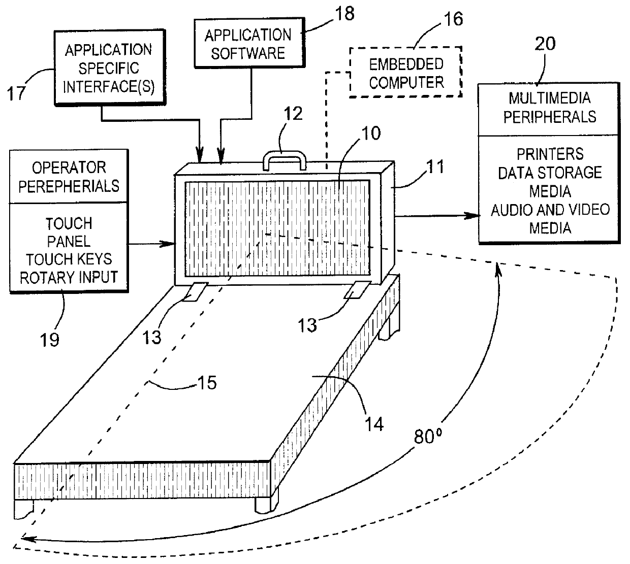
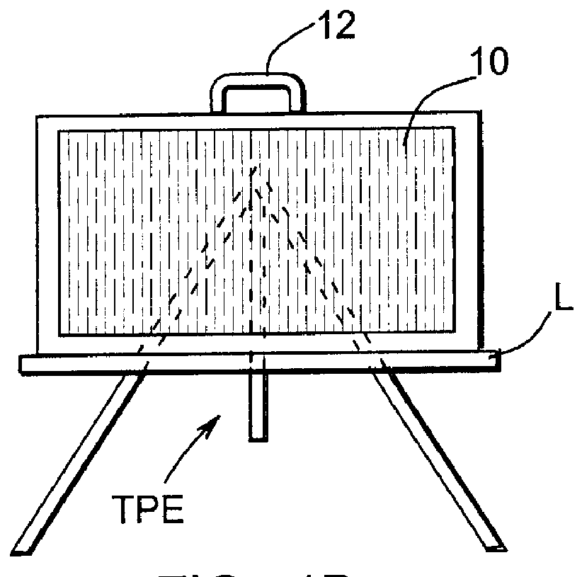
Referring to FIG. 1a, a flat display panel 10 (of the matrix type with row and column electrode arrays locating and defining pixel sites) in a luggage style case 11, having optional handle 12 and detachable and optional leg brace brackets 13, is located at one end of a conference table 14. The flat panel display unit 10 could be hung on a wall or from a ceiling or mounted on a tripod easel (FIGS. 1b or 1c) and has a wide viewing angle (160 degrees or 80 degrees to each side of centerline 15). An embedded computer is subsystem 16 (element "A" in FIGS. 5a, 5b and 5c). The embedded computer 16 is interfaced with electronic drive (element D in FIGS. 5a, 5b and 5c) for the row and column electrode arrays by application of specific interface 17 (elements "B" and "C" in FIGS. 5a, 5b and 5c). Embedded computer 16 is provided with application specific software, indicated diagrammatically at 18 (element "E" in FIGS. 5a, 5b and 5c). The presentation display may also have various operator peri...


PUM


Abstract

A high brightness presentation display system includes: a transparent display panel having a viewing side and a non-viewing side, furcated row electrode array, furcated column electrode array defining matrix crosspoints and an electro-responsive display producing medium at said matrix crosspoints. Row electrode drive circuitry is connected to selectively drive electrodes in the row electrode array and column electrode drive circuitry is connected to selectively drive electrodes in the column electrode array such that conjoint voltages on selected row and column electrodes operate the display. The furcated electrode spacing and interelectrode spacings are such as to enhance discrimination, and the multiple sub-pixels due to the furcations of electrodes enhance brightness. Optical sensor positioned on the non-viewing side for viewing through the transparent display panel at a predetermined position from the viewing side of the transparent display panel is activated by a remote source producing a control beam of optical energy through the transparent display panel. Optionally, electrically generated icons displayed on the panel can be used to locate the sensors. Color displays and displays having high visibility in sunlight are disclosed.

Description

BACKGROUND AND BRIEF DESCRIPTION OF THE INVENTIONThis invention relates to generally flat panel display screens and systems, particularly to display systems with enhanced viewing and, still more particularly, to AC plasma display panel (PDP) systems which are particularly adapted for presentation displays and large viewing angle and a display having high visibility in sunlight.It is common for presentation display systems to incorporate cathode ray tube (CRT) type or projection displays. Such displays have limited viewing angles, reduced brightness and contrast, and are very bulky in large viewing area or screen sizes. Projection-type display systems require space for the projection path, a bulky screen, and the pixels do not have good discrimination ratios. Flat LCD displays have limited viewing angles and are expensive in large sizes. All of these systems are of relatively low brightness and require dimming of room illumination for viewing purposes.Objects of the present invention...

Claims


Application Information

Patent Timeline
IPC IPC(8): G06F3/033G09G3/28H01J17/49G06F3/042G09G3/297G09G3/298H01J11/12
CPCG09G3/297H01J11/12G09G3/2986G09G3/2983
Inventor STOLLER, RAY A.
Owner PIONEER CORP
Why Eureka
Try Eureka