Micrometer

a micrometer and micrometer technology, applied in the field of micrometers, can solve the problems of increasing measurement errors, increasing production costs, and no single micrometer can be used for single-handed and double-handed operations

Inactive Publication Date: 2002-10-15
MITUTOYO CORP
View PDF15 Cites 10 Cited by
  • Summary
  • Abstract
  • Description
  • Claims
  • Application Information

AI Technical Summary

Problems solved by technology

No single micrometer can be used for both of single-handed operation and double-handed operation.
However, according to the above arrangement, since the constant-force device of the first conventional art functions during single-handed operation and the constant-force device of the second conventional art functions during double-handed op...

Method used


Image

  • Micrometer
  • Micrometer
  • Micrometer

Examples


Embodiment Construction

)

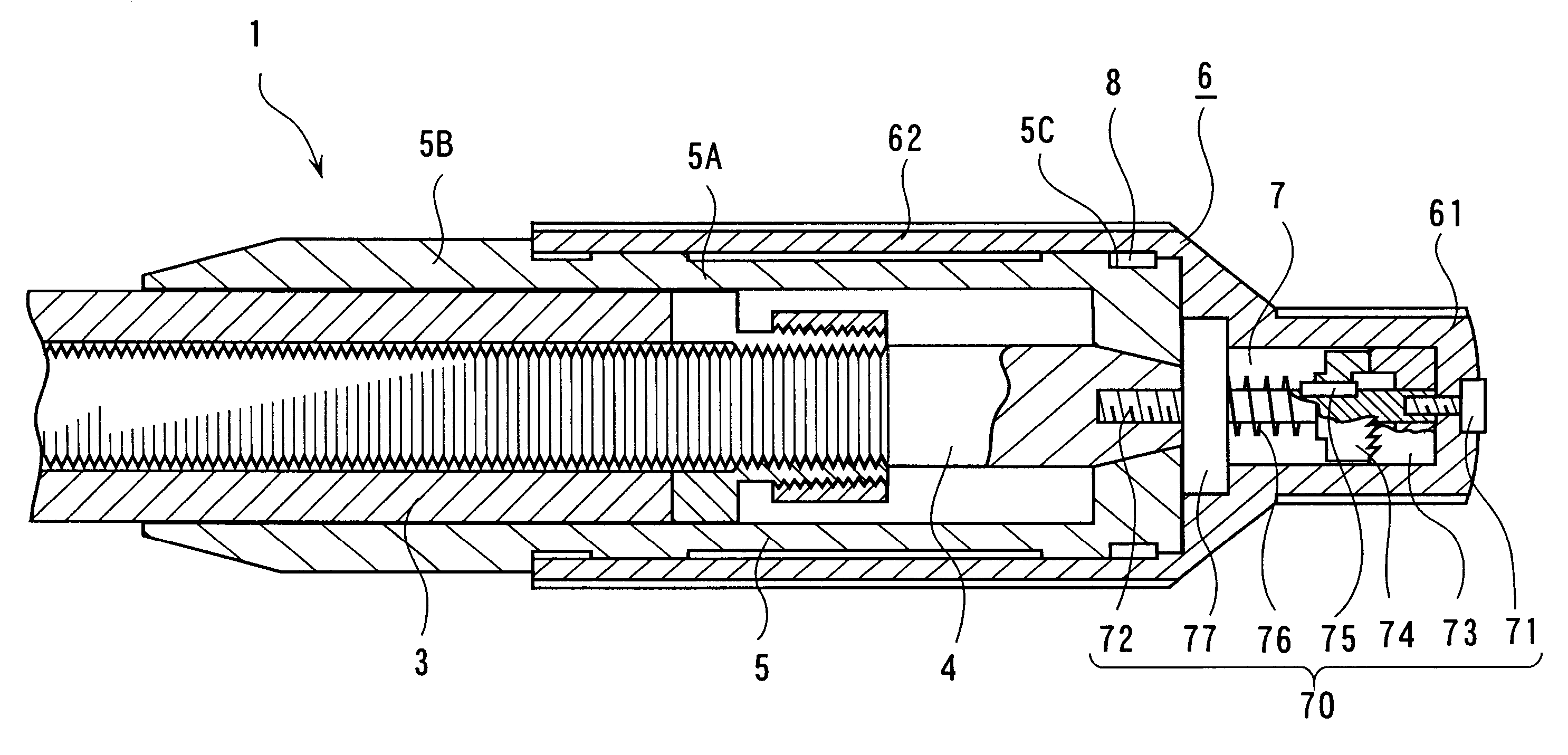
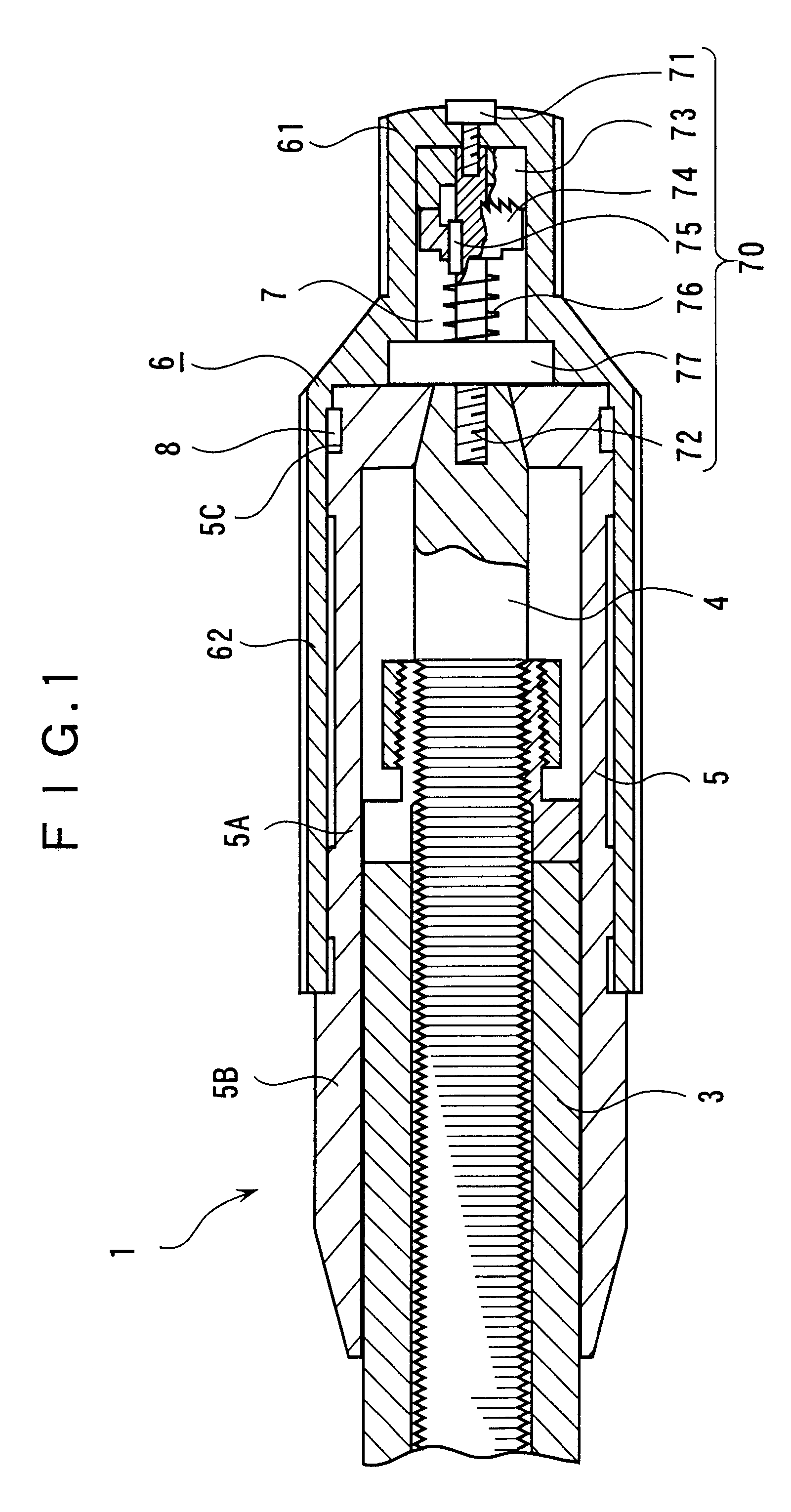
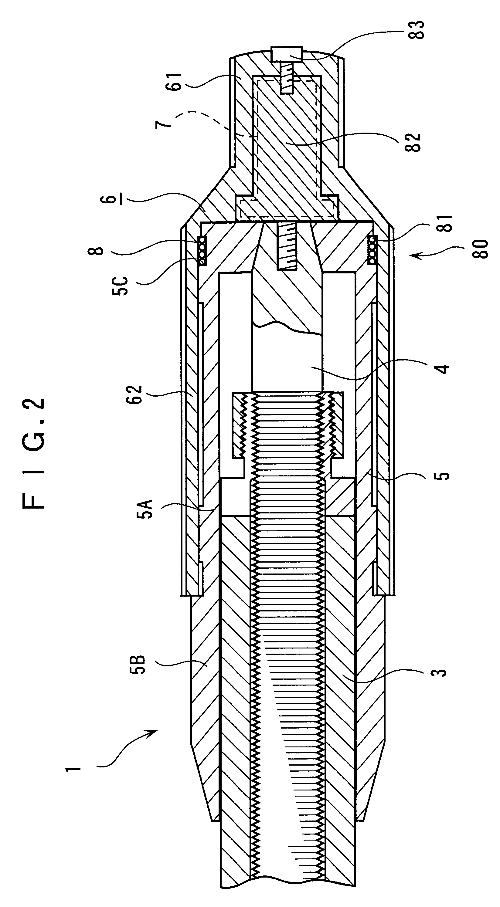
As shown in FIGS. 1 and 2, a micrometer 1 according to the present embodiment has an approximately U-shaped frame (not shown), an anvil (not shown) held at one end of the frame, a spindle 4 screwed to the other end of the frame through a retainer sleeve 3 and moved toward and away from the anvil, a thimble 5 secured to the spindle 4 and fitted to an outer circumference of the retainer sleeve 3 as in the micrometer 100 of the aforesaid first conventional art.

On an outer side of an end remote from the end opposing the anvil, the micrometer 1 is provided with an operation sleeve 6 rotatable relative to the spindle 4 and integrally having a first operation section 61 with a smaller diameter than the diameter of the retainer sleeve 3 and a second operation section 62 fitted to an outer circumference of the thimble 5.

A section 5A of the thimble 5 fitted to the second operation section 62 is thinner than a section 5B not fitted to the second operation section 62. A circular groove 5C is f...


PUM


Abstract

A thimble (5) and a spindle (4) are rotated through a first constant-force device (70) by rotating an operation sleeve (6) integrally having a first operation section (61) and a second operation section (62). When a more than predetermined load is applied to the spindle (4), the first constant-force device (70) is actuated to spin the operation sleeve (6) idly. Since the operation sleeve (6) integrally has the first operation section (61) and the second operation section (62), both double-handed operation for holding the frame by left hand and rotating the first operation section (61) by right hand and single-handed operation for holding the frame and rotating the second operation section (62) with a single-handed are possible while retaining the same operability as in conventional operation during measurement.

Description

1. Field of the InventionThe present invention relates to a micrometer for measuring dimension of a workpiece such as length and thickness.2. Description of Related ArtIn FIG. 3, a conventional micrometer 100 (first conventional art) has an approximately U-shaped frame 101, an anvil 102 held at one end of the frame 101, a spindle 104 screwed to the other end of the frame 101 through a retainer sleeve 103 and moved toward and away from the anvil 102, a thimble 105 secured to the spindle 104 and fitted to an outer circumference of the retainer sleeve 103, and a ratchet mechanism 106 provided to a rear end of the spindle 104 for idly spinning when a more than predetermined load is applied to the spindle 104.Though not shown, the ratchet mechanism 106 has a pair of ratchet wheels meshing with each other and a compression helical spring for biasing the ratchet wheels in a direction to mesh each other, the ratchet wheels spinning idly when a more than predetermined load is applied to the ...

Claims


Application Information

Patent Timeline
IPC IPC(8): G01B3/18
CPCG01B3/18
Inventor SAEKI, AKITOMO
Owner MITUTOYO CORP
Why Eureka
Try Eureka