Water purifier and switchover valve

A water purifier and water purification technology, applied to chemical instruments and methods, water supply devices, water treatment sites, etc., can solve problems such as inconvenient operation, prevent the decline in workability, realize miniaturization, and reduce the number of parts Effect

Active Publication Date: 2015-01-21
MITSUBISHI RAYON CLEANSUI CO LTD
View PDF4 Cites 0 Cited by
  • Summary
  • Abstract
  • Description
  • Claims
  • Application Information

AI Technical Summary

Problems solved by technology

[0006] while using Figure 19 When the double support rod 102 is shown, the lower view of the unshown raw water discharge outlet, the spray discharge outlet and the clean water discharge outlet arranged at the bottom of the water purifier 101 will be arranged in the water purifier by the double support rod 102. The part P on the front side of 101 is covered, and there are problems such as inconvenient operations when cleaning dishes, etc.

Method used


Image

  • Water purifier and switchover valve
  • Water purifier and switchover valve
  • Water purifier and switchover valve

Examples


Embodiment Construction

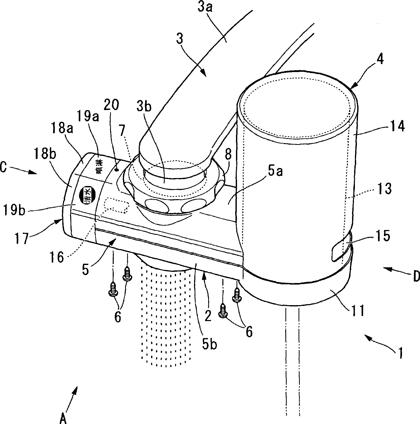
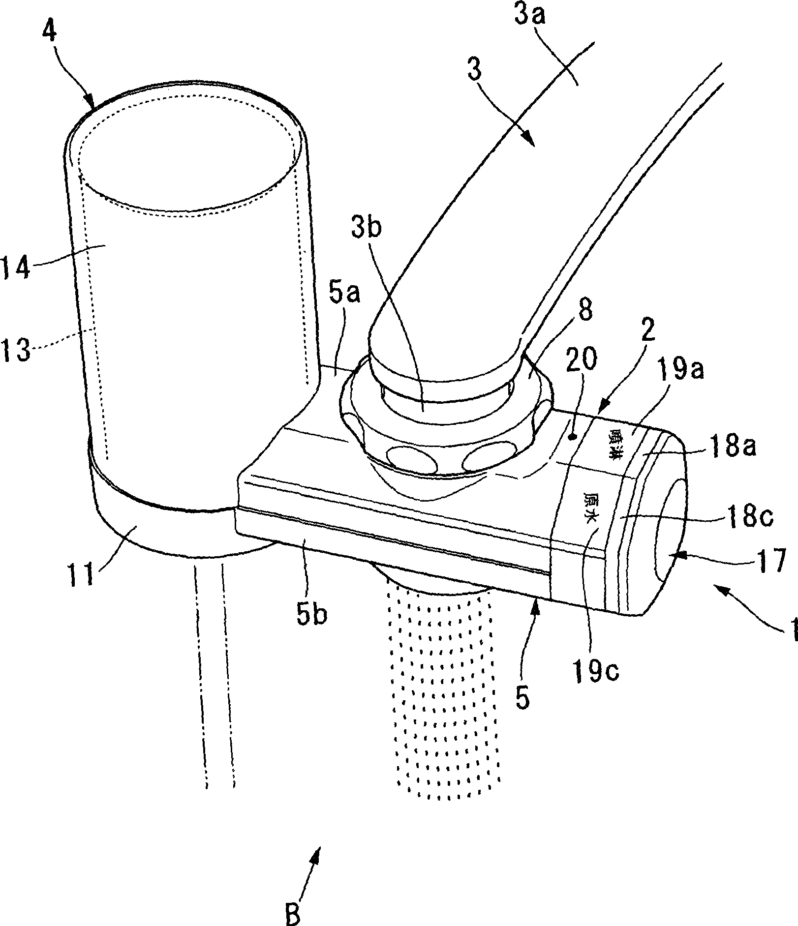
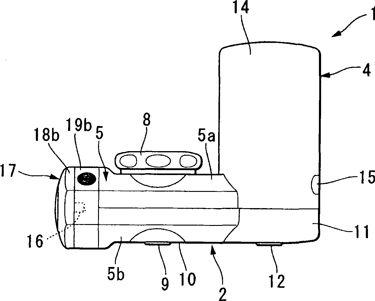
[0089] Below, refer to Figure 1 to Figure 13 The first embodiment of the present invention will be described. Here, the so-called front-rear direction in the first embodiment refers to the state where the longitudinal direction of the water purifier 1 is vertically installed relative to the arm portion 3a of the faucet 3, standing on the front of the faucet 3, that is, standing on the extension of the arm portion 3a. The front-back direction seen by the online user (the same applies to the second and third embodiments below).

[0090] exist Figure 1 to Figure 8 Among them, 1 represents the water purifier of the first embodiment. The water purifier 1 is mainly composed of a substantially octagonal column-shaped water purifier body 2 and a substantially cylindrical purifying part (purifying device) 4, and the bottom of the purifying part 4 substantially along the vertical direction is combined with a purifying part substantially along the horizontal direction. One end porti...


PUM


Abstract

A water purifier reduced in size and having improved workability, which are achieved without impairing its operability. The water purifier has a case body (5) that is provided with a receiving opening (7) attached to a faucet (3) and receiving raw water from the faucet (3), a raw-water discharge opening (9) for discharging the raw water without treatment, and a purified-water discharge opening (12) for discharging water received from the receiving opening (7) and purified in a purification section (4). Switchover operation means (17) is provided at either the left or the right of the water purifier and enables switchover between a flow path from the receiving opening (7) to the purification section (4) and a flow path from the receiving opening (7) to the raw-water discharge opening (9). The centers of the receiving opening (7) and the purified-water discharge opening (12) and the center of the raw-water discharge opening (9) are arranged on a cross-section (S) in the center in the front-rear direction of the case body (5).

Description

technical field [0001] The invention relates to a water purifier and a switching valve. Background technique [0002] This application claims priority based on Patent Application No. 2006-124107 filed in Japan on April 27, 2006 and Patent Application No. 2007-023484 filed in Japan on February 1, 2007, the entire contents of which are incorporated herein. [0003] Known so far have a kind of so-called faucet direct connection type water purifier that is directly installed on the faucet. In such a water purifier, there are generally a raw water discharge port that directly discharges raw water, a spray discharge port that discharges raw water in a shower, and a clean water discharge port that discharges purified water. The discharge state of the water can be selected. Considering that most users are right-handed, the switching lever is mostly set on the right side of the water purifier body in a freely swingable state, but it exists on the right side when operated by left-ha...

Claims


Application Information

Patent Timeline
Patent Type & Authority Patents(China)
IPC IPC(8): C02F1/28E03C1/10C02F1/44
CPCC02F1/28E03C2201/30E03C1/08C02F2307/06E03C2201/40C02F1/003E03C1/0404C02F1/444
Inventor 石川刚士畠山厚森田至厚岩城大
Owner MITSUBISHI RAYON CLEANSUI CO LTD
Why Eureka
Try Eureka