Sealed rectangular battery and manufacturing method for the same

a manufacturing method and rectangular battery technology, applied in the field of rectangular battery, can solve the problems of increasing the internal resistance of the battery, reducing the thickness of the battery, and limiting the slimness of the battery

Inactive Publication Date: 2003-06-17
FDK CORP
View PDF5 Cites 52 Cited by
  • Summary
  • Abstract
  • Description
  • Claims
  • Application Information

AI Technical Summary

Problems solved by technology

When developing a rectangular nickel-hydroxide battery, the construction of the positive electrode terminal with its comparatively large number of components places limitations on how slim the battery can be made.
Such conventional designs make reductions in the thickness of the battery problematic.
There is a further problem in that the complex construction of the positive electrode terminal raises the internal resistance of the battery.
When the resinous parts of the positive electrode terminal, such as the gasket, are located close to

Method used


Image

  • Sealed rectangular battery and manufacturing method for the same
  • Sealed rectangular battery and manufacturing method for the same
  • Sealed rectangular battery and manufacturing method for the same

Examples


first embodiment (

1. First Embodiment (A Rectangular Nickel-Hydroxide Battery)

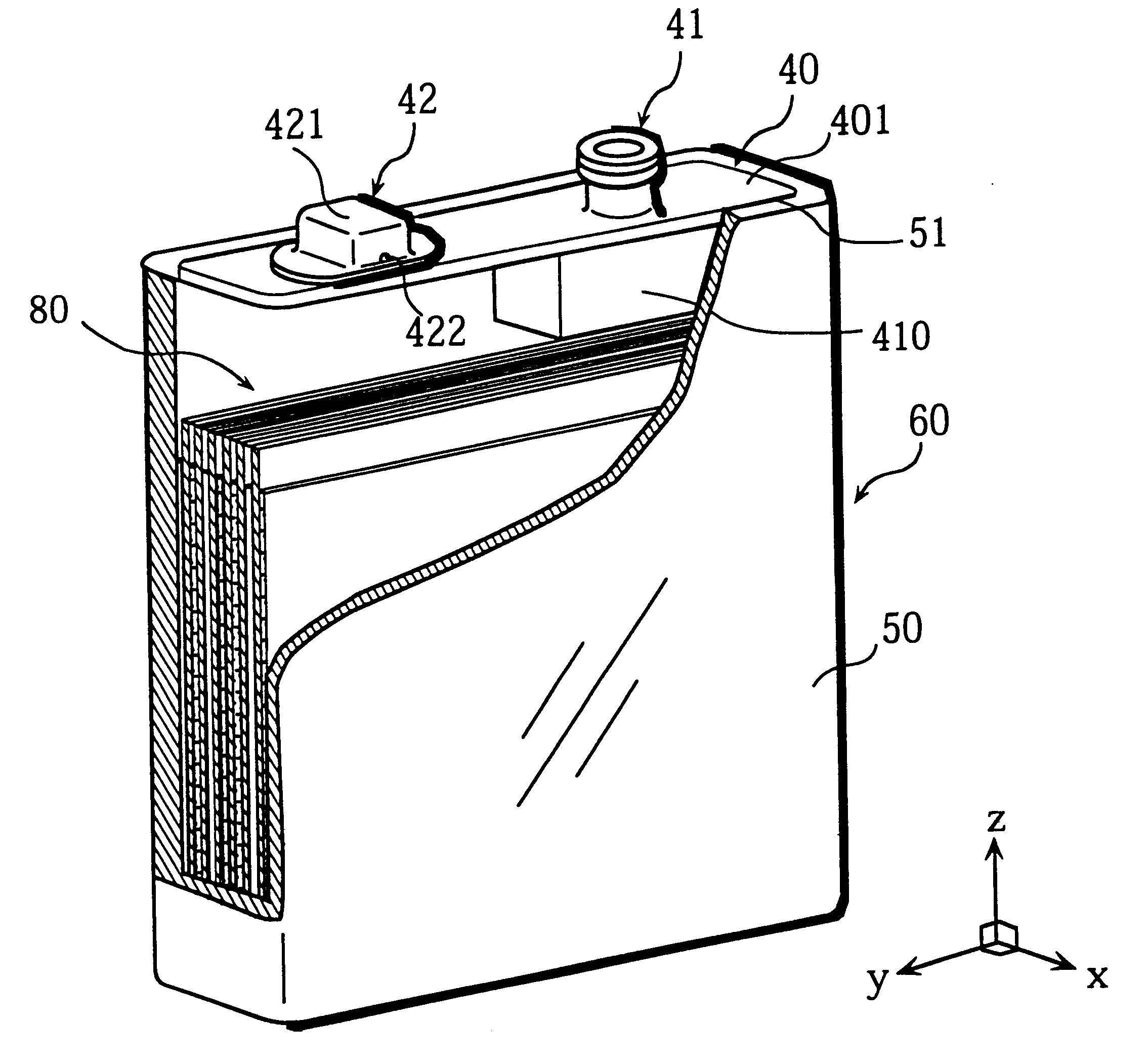
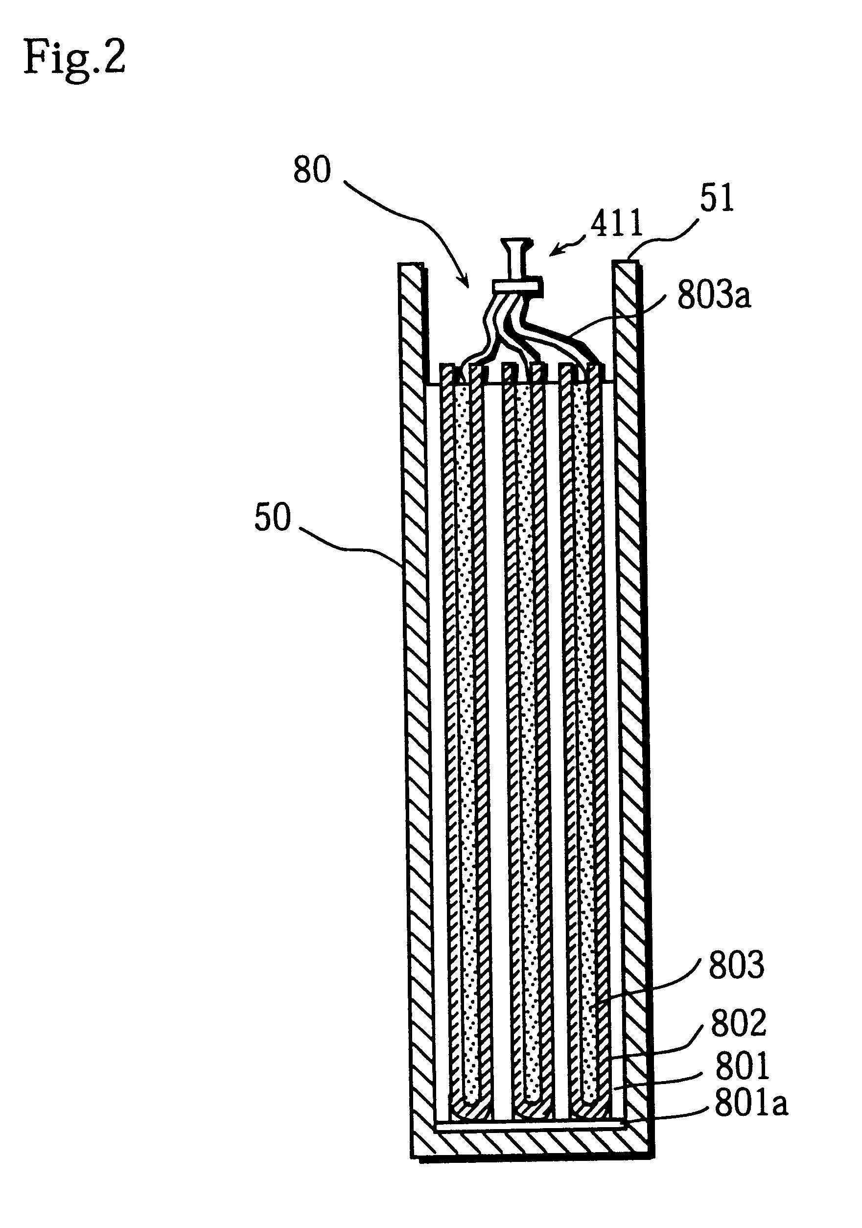
FIG. 1 shows a partial cross-section of a rectangular nickel-hydroxide (Ni--H) battery 60 (hereafter simply "battery 60"). As shown in FIG. 1, the battery 60 has a generator element 80 that is enclosed within an external casing 50. A sealing cap 40 is laser-welded to a rim surrounding an opening 51 of the external casing 50 to seal the battery 60. An electrode terminal (here, a positive electrode terminal) 41 and a safety valve 42 are provided on the upper surface of the sealing cap 40.

1--1 Composition of the Generator Element

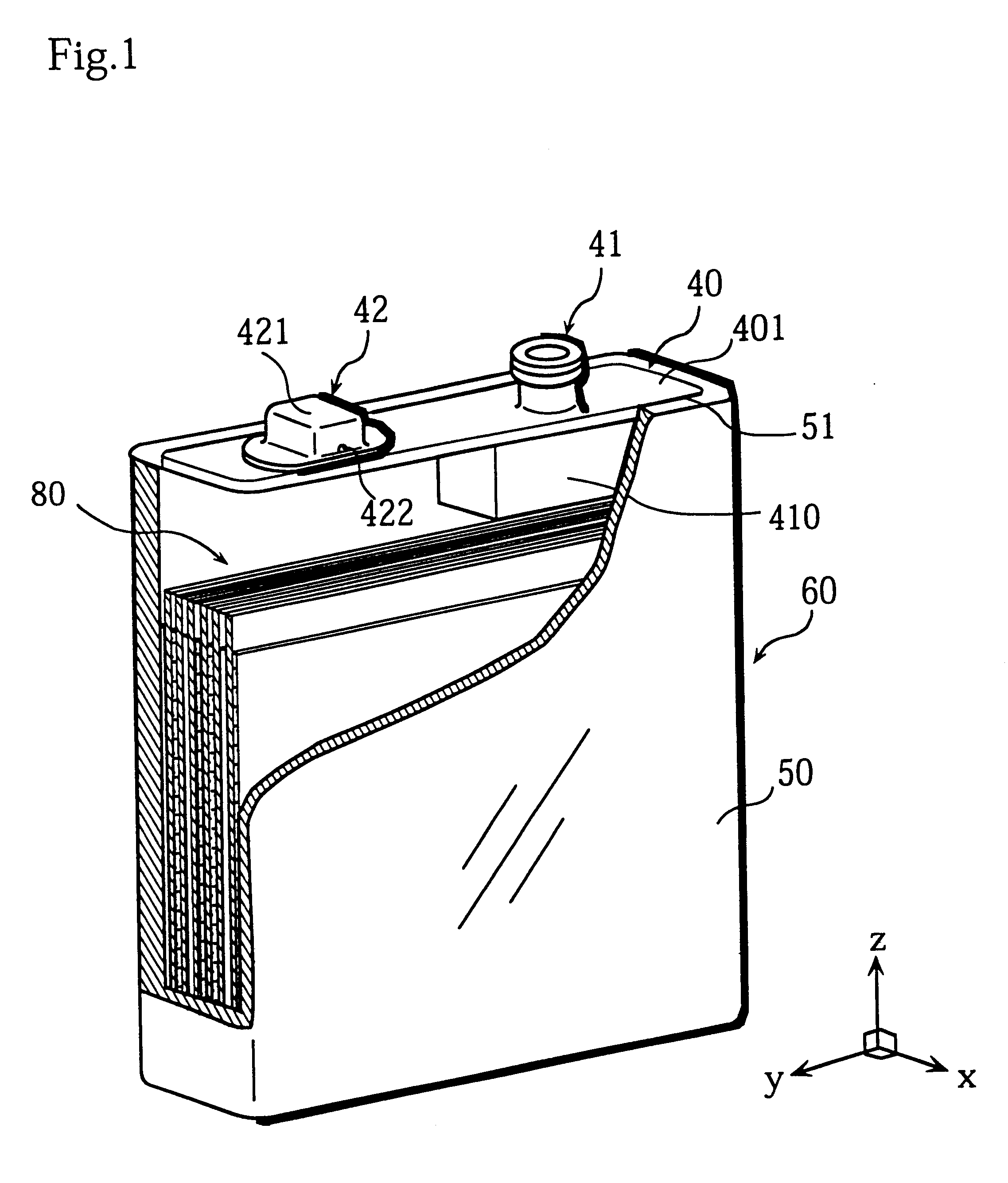
FIG. 2 shows a cross-section of the external casing 50 enclosing the generator element 80, taken across the battery in the thickness direction. As shown in the drawing, the generator element 80 is composed of a plurality of strip-like negative electrode plates 801 and positive electrode plates 803 that are alternately arranged with separators 802 made of an insulating material in-between.

The negative e...

second embodiment

4. Second Embodiment

FIGS. 6A to 6C show the construction of a sealing cap 70 for a rectangular nickel hydroxide battery that is a second embodiment of the present invention. As can be seen from FIGS. 6A to 6C, the second embodiment differs from the first embodiment in that the positive electrode terminal 71 is arranged in the center of the sealing plate 701. As a result, the insulator plate 710 and terminal rivet 711 are positioned in the center of the underside of the sealing plate 701. The safety valve 72 that houses the valving element 723 is positioned in the same way as the safety valve 42. This construction has the same effects as the first embodiment. The ability to adapt the battery in this way is thought to be especially helpful when designing batteries for different purposes.

In the present invention, the positive electrode terminal and the safety valve may be arranged on the main surface of the sealing plate at different distances from the center of the sealing plate.

third embodiment

5. Third Embodiment

FIG. 7 is a perspective drawing showing the overall construction of a battery pack (combined battery) 900 that includes a plurality of batteries 60 according to the first embodiment of the present invention.

The battery pack 900 has an insulating frame 901 in which a plurality (three in the illustrated example) of batteries 60 are inserted. This makes it possible to use the plurality of batteries as a single battery. The batteries 60 are arranged inside the frame 901 in the direction shown as W' in FIG. 7, which is to say, with their narrowest sides together and the safety valves 42 and positive electrode terminal 41 arranged in a straight line. To prevent short circuits between adjacent external casings 50, insulating sheets 902 are placed between adjacent batteries 60 in the frame 901.

Adjacent safety valves 42 and positive electrode terminals 41 are connected to one another using connectors 904 that pass through breakers 903. These breakers 903 are arranged into ...


PUM


Abstract

A sealed rectangular battery has a conductive battery case including an external casing and a sealing cap. The external casing encloses a generator element and is sealed by attaching the sealing cap using heat. The battery includes an electrode terminal with an opposite polarity to the battery case, and a safety valve. The safety valve includes a cap that is charged with the same polarity as the battery case and a valving element that covers a vent hole. The electrode terminal and safety valve are provided separately at different positions on the battery case. This construction is simpler than conventional batteries where the safety valve is integrally formed with an electrode terminal, which means that the electrode terminal can be miniaturized. This battery also has improved internal resistance.

Description

This application is based on applications Nos. H11-273933, H11-273934, and H11-310084 filed in Japan, the contents of which are hereby incorporated by reference.(1) Field of the InventionThe present invention relates to a sealed rectangular battery and a manufacturing method for the same. In particular, the invention relates to an improvement in the construction of the sealing cap and terminals.(2) Related ArtA rapid increase in the use of small electronic appliances has been observed in recent years. Such appliances include mobile phones and personal digital assistants (PDAs), and need to be capable of relatively long periods of continuous operation. As a result, much research is being conducted into the development of batteries with high energy densities that can be used to power these appliances.Small electronic appliances tend to be powered by sealed rectangular batteries. Compared to other batteries, rectangular batteries have the advantage of taking up little space. This makes...

Claims


Application Information

Patent Timeline
IPC IPC(8): H01M2/06H01M10/28H01M10/24H01M2/12H01M2/30H01M2/02H01M10/34H01M50/176H01M50/55H01M50/553H01M50/562
CPCH01M2/06H01M2/1229H01M10/287H01M2/0217Y02E60/124H01M10/345H01M2/30Y02E60/10H01M50/103H01M50/325Y02P70/50H01M50/562H01M50/55H01M50/553H01M50/176H01M10/34
Inventor NAGASE, TAKASHIHAMAMATSU, TAKEOINOUE, MASAOASANUMA, HIDEYUKIHINOTSU, NAOYOSHI
Owner FDK CORP
Why Eureka
Try Eureka