

Electronic apparatus having cooling unit for cooling heat-generating component
a technology of cooling unit and heat-generating component, which is applied in the direction of electrical apparatus casing/cabinet/drawer, instrument, and semiconductor/solid-state device details, etc., can solve the problems of degrading the cooling performance of microprocessors, unable to positively draw and discharge air within the housing, and the cooling air between the cooling air and the heat sink cannot be efficiently executed, so as to enhance the heat dissipation
- Summary
- Abstract
- Description
- Claims
- Application Information
AI Technical Summary
Benefits of technology
Problems solved by technology
Method used
Image

Examples
first embodiment
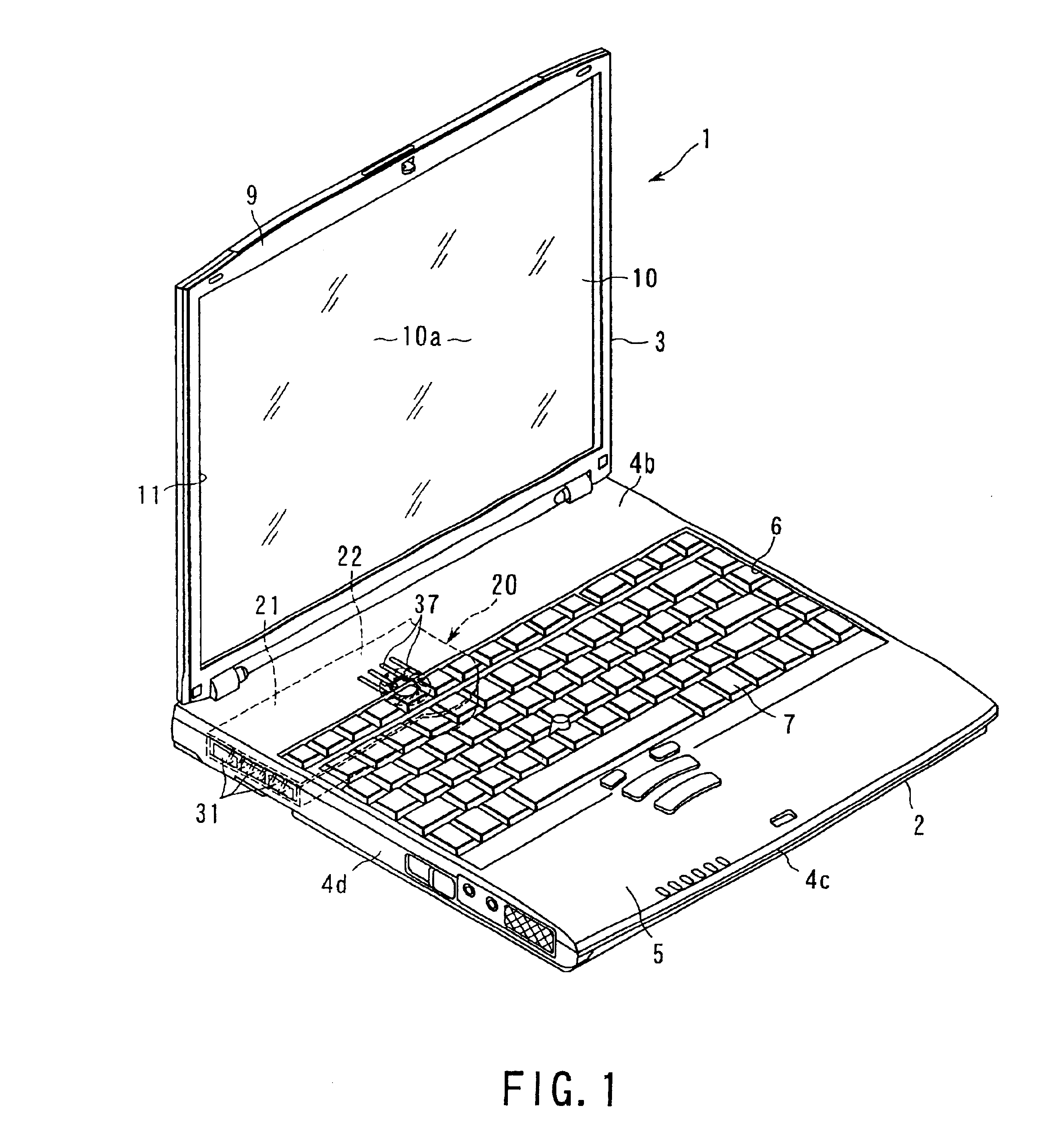
Referring to FIGS. 1-5, a portable computer according to the invention will be described.
FIG. 1 shows a portable computer 1 as an electronic apparatus. The portable computer 1 comprises a computer main unit 2, and a display unit 3 supported by the main unit 2. The computer main unit 2 includes a housing 4. The housing 4 is in the shape of a flat box, and includes a bottom 4a, upper surface 4b, front wall 4c, right and left sidewalls 4d and rear wall 4e. The front wall 4c, sidewalls 4d and rear wall 4e extend downwardly from the respective outer peripheral edges of the upper surface 4b, thereby forming the peripheral walls of the housing 4. The upper surface 4b of the housing 4 has a palm rest 5 and keyboard attachment portion 6. The palm rest 5 forms the front edge portion of the housing 4. The keyboard attachment portion 6 is located behind the palm rest 5. A keyboard 7 is attached to the keyboard attachment portion 6.
The display unit 3 comprises a display housing 9, and a liquid c...
third embodiment
Referring to FIGS. 7 and 8, the invention will be described.
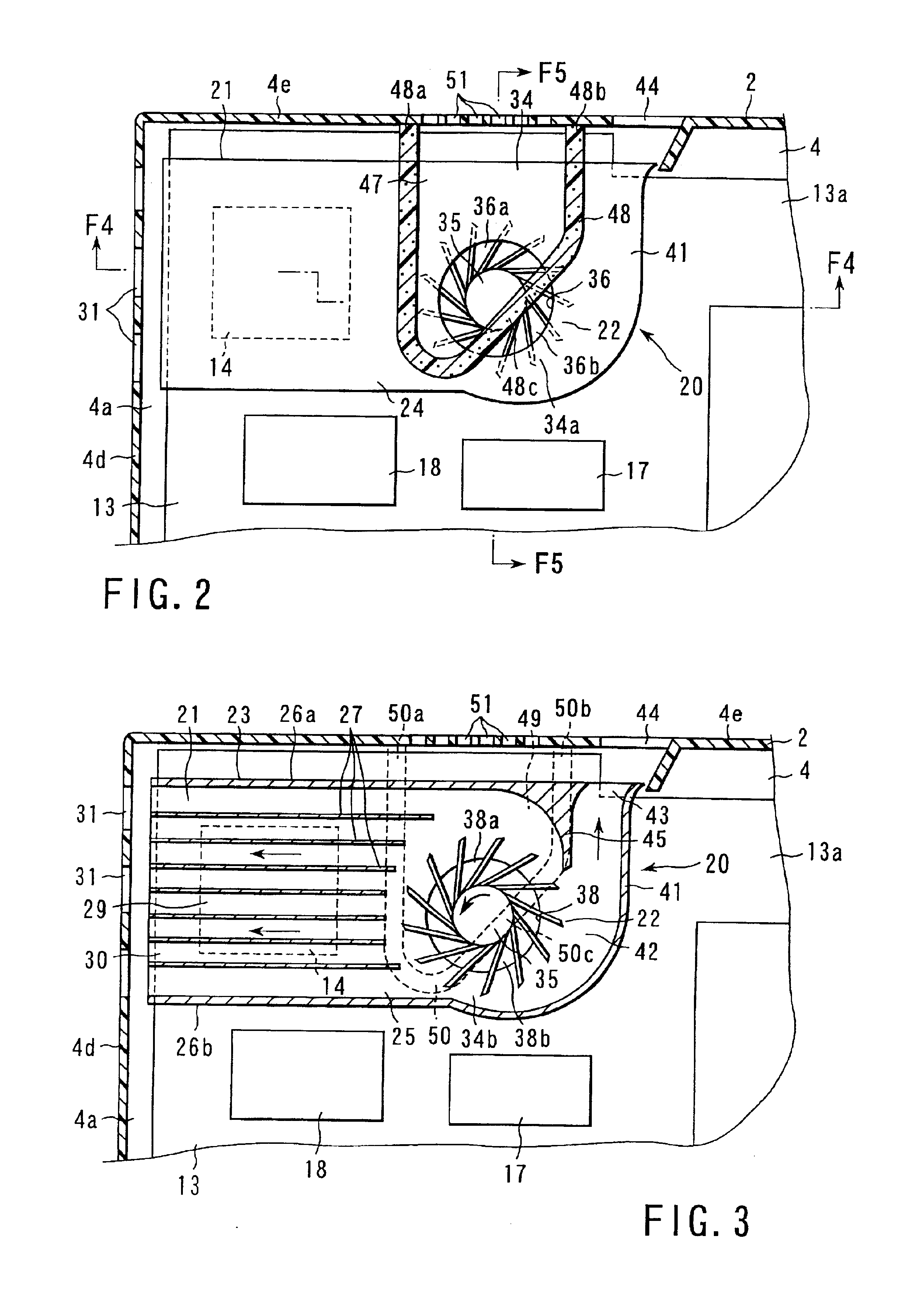
In the third embodiment, both the first and second suction ports 36 and 38 of the fan casing 34 open to the interior of the housing 4. In this structure, when the impeller 35 of the electromotive fan 22 rotates, the air in the housing 4 is introduced into the fan casing 34 through the first and second suction ports 36 and 38. Part of the introduced air is discharged from the outer peripheral portion of the impeller 35 to the upstream end of the first air passage 29 as indicated by arrows A in FIG. 7. The other part of the air is discharged from the outer peripheral portion of the impeller 35 to the upstream end of the second air passage 42 as indicated by arrow B in FIG. 7. Thus, the air in the housing 4 is simultaneously introduced into the heat sink 21 through the first air passage 29, and discharged to the outside of the housing 4 through the second air passage 42.
In this structure, substantially the entire outer periphe...
fourth embodiment
Referring to FIGS. 9 and 10, the invention will be described.
The fourth embodiment differs from the first embodiment in the position of the cooling unit 20 with respect to the housing 4. The basic structure of the cooling unit 20 is similar to that in the first embodiment.
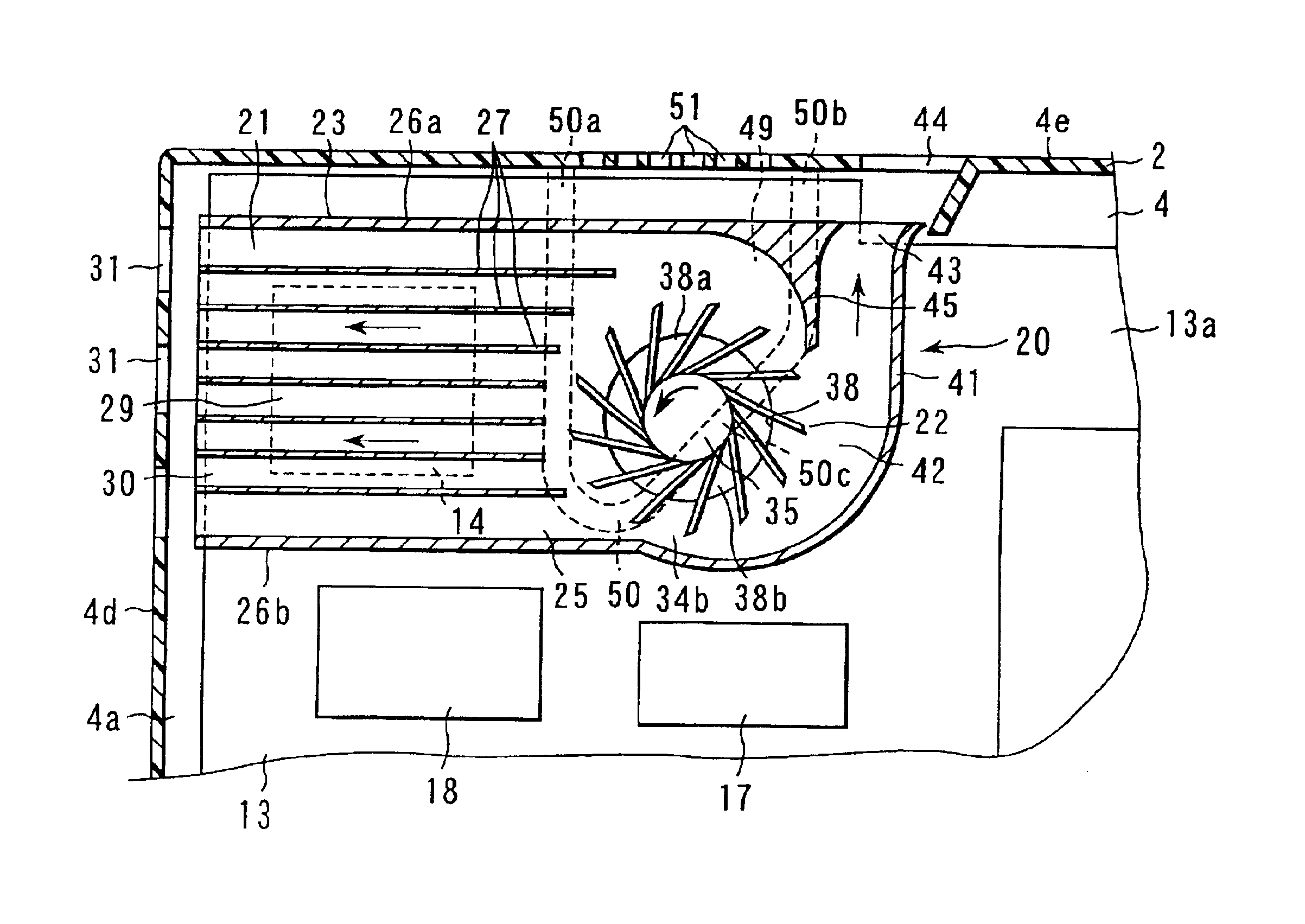
As shown in FIG. 9, the heat sink 21 is housed in the housing 4, extending along the depth of the housing 4. The discharge port 30 of the first air passage 29 of the heat sink 21 is adjacent to the rear wall 4e of the housing 4, and opposes the first outlets 31 formed in the rear wall 4e.
The electromotive fan 22 is located in front of the heat sink 21. The discharge port 43 of the second air passage 42 of the fan casing 34 is adjacent to the sidewall 4d, and opposes the second outlet 44 formed in the sidewall 4d. Further, second inlets 51 are formed in the sidewall 4d. The second inlets 51 communicate with the first areas 36a and 38a of the first and second suction ports 36 and 38 via the first and second external...
PUM
 Abstract
Description
Claims
Application Information