Switchable-bandwidth optical receiver

a transceiver and optical receiver technology, applied in the direction of pulse technique, instruments, using reradiation, etc., can solve the problem of not being able to achieve the standard-compliant operation of multiple bit-rates, the maximum receiver bandwidth limit of 1.5 ghz is not previously overcome, etc., to achieve the effect of higher performan

Inactive Publication Date: 2005-03-01
IBM CORP
View PDF12 Cites 142 Cited by
  • Summary
  • Abstract
  • Description
  • Claims
  • Application Information

AI Technical Summary

Benefits of technology

, the above describes embodiments of a switchable-bandwidth optical receiver. Three general topologies that could be used to produce a switchable-bandwidth optical receiver have been described, along with specific implementation examples in each topology. An optical receiver with a dynamically controllable bandwidth will allow transceivers that are functionally capable of being included in optical links with autonegotiated transmission rates. The ability to detect the operating bit-rate and adjust the transmission and/or reception of a transceiver t

Problems solved by technology

However, optical transceiver users may require future transceivers to inter-operate with lower-speed ‘legacy’ transceivers.
However, the ability to inter-operate with legacy transceivers is a feature that has not previously been achieved in successive generations of optical transceivers.
That is, the problem of producing an optical transceiver capable of standard-compliant operation at multiple bit-rates has not p

Method used


Image

  • Switchable-bandwidth optical receiver
  • Switchable-bandwidth optical receiver
  • Switchable-bandwidth optical receiver

Examples


Embodiment Construction

)

The invention will now be described in more detail by way of example with reference to the embodiment(s) shown in the accompanying figures. It should be kept in mind that the following described embodiment(s) is / are only presented by way of example and should not be construed as limiting the inventive concept to any particular physical configuration.

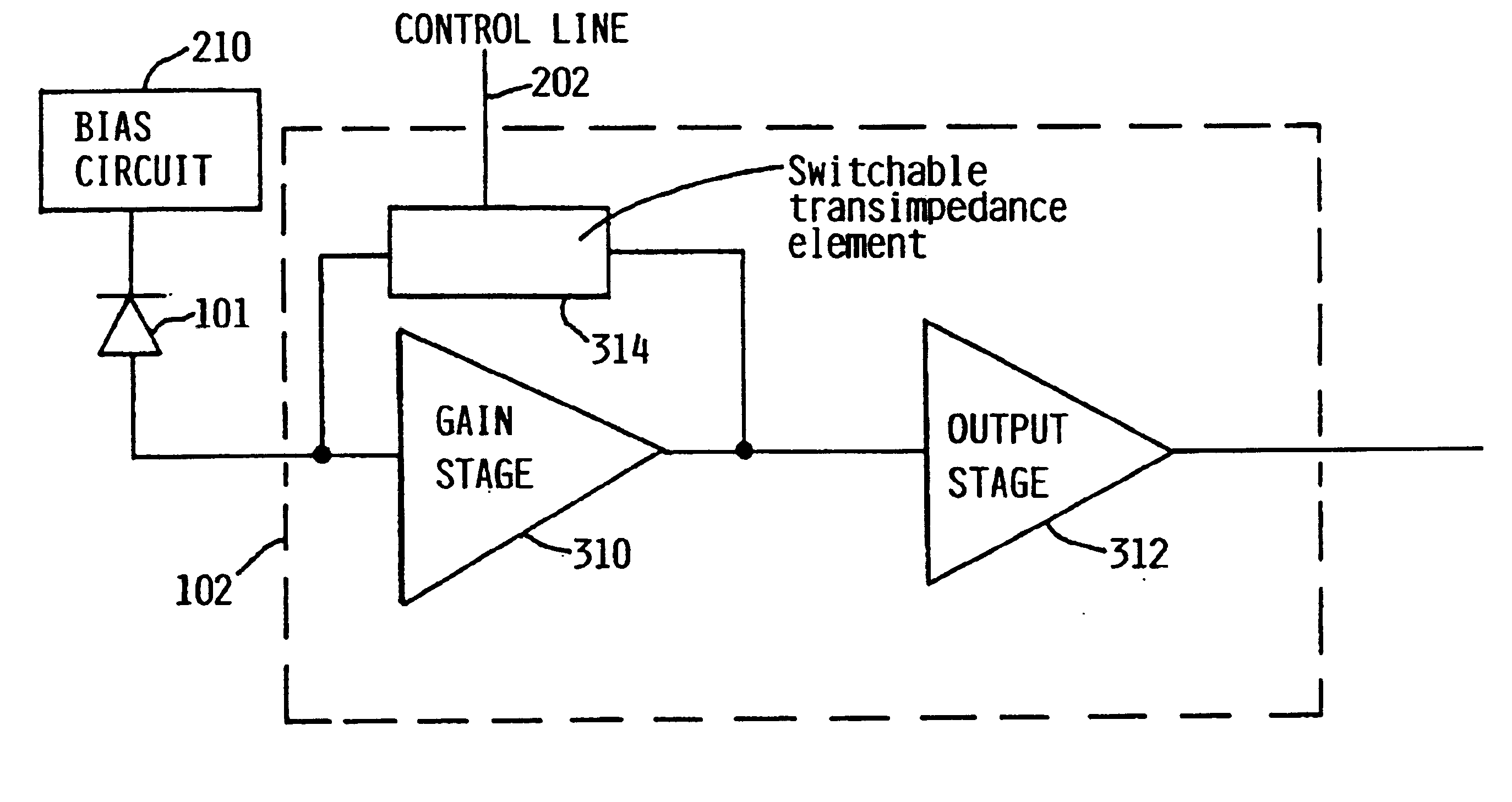
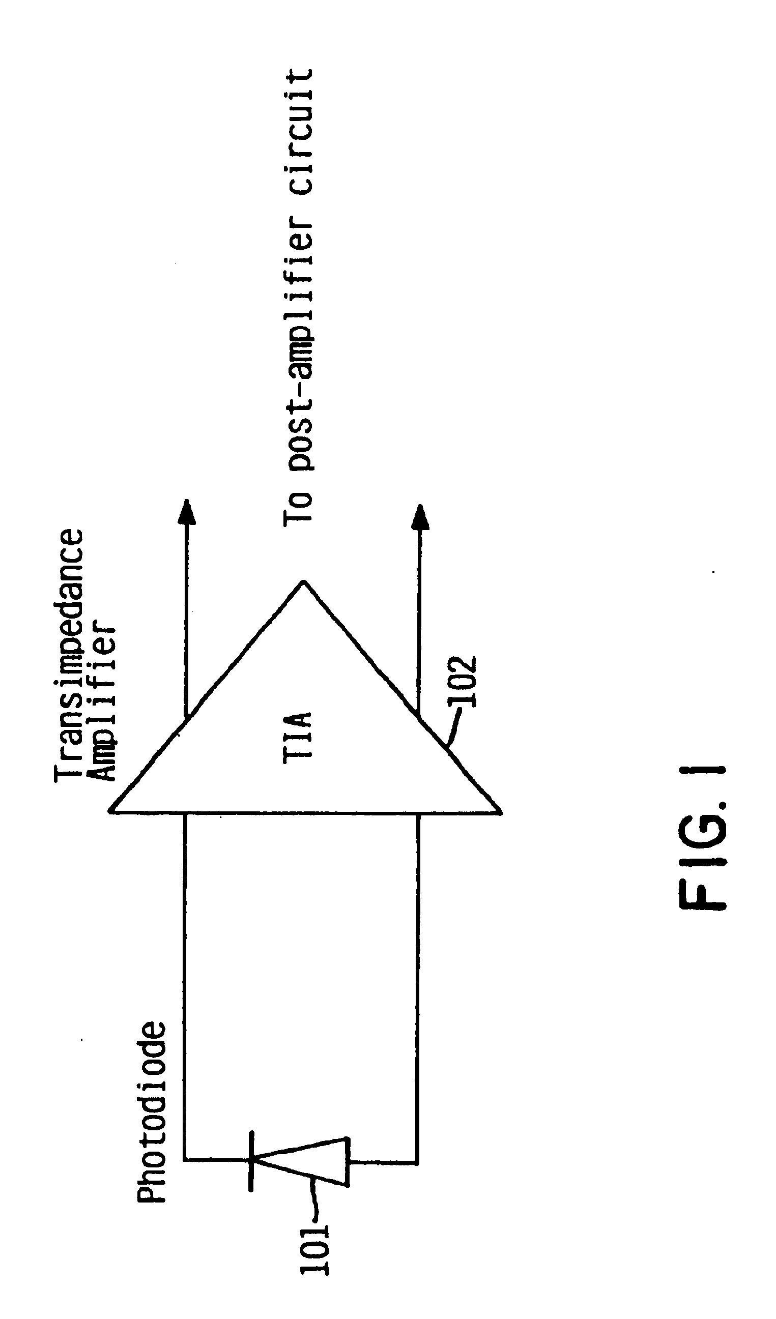
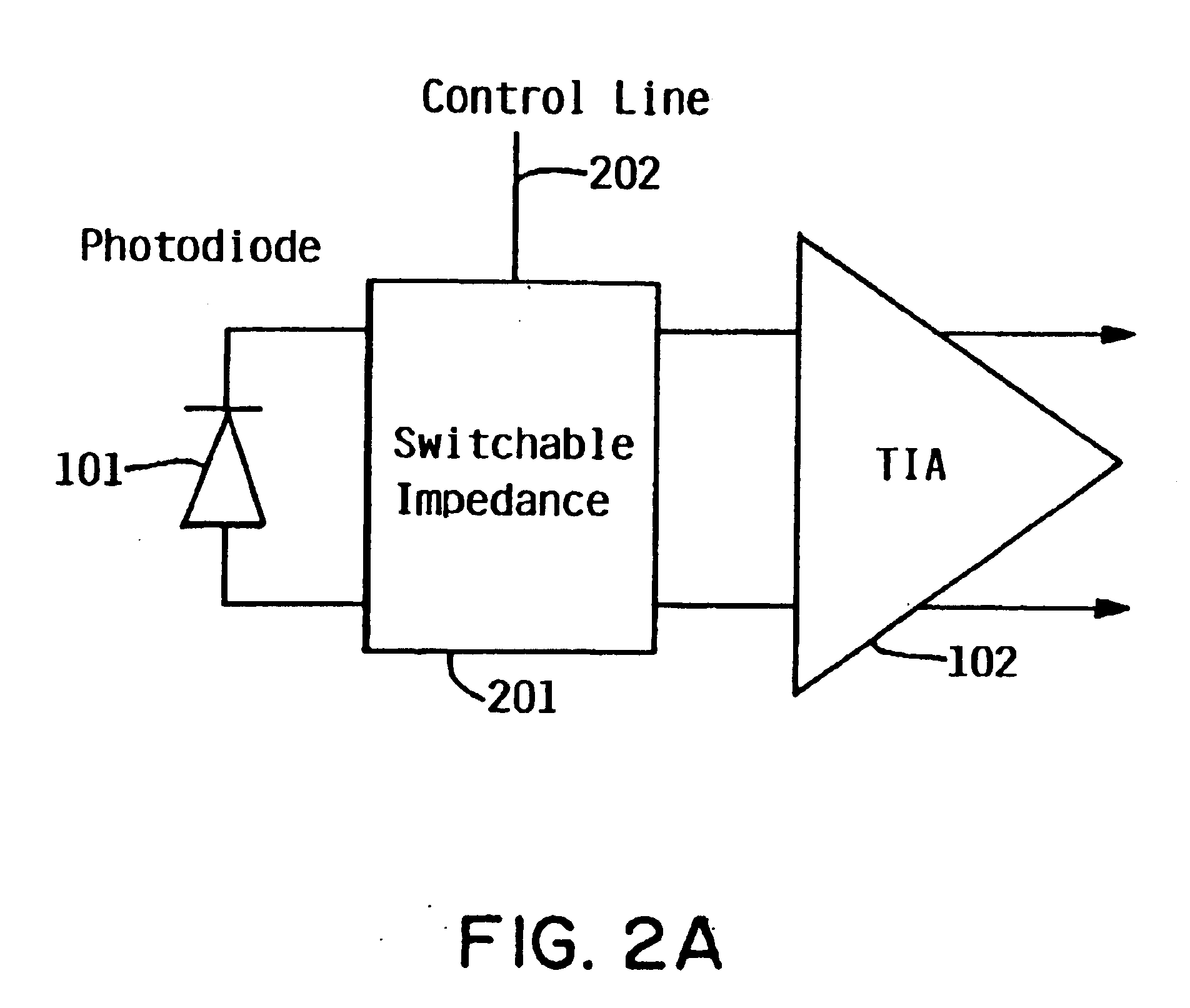
FIG. 1 illustrates a typical optical receiver front-end. An optical receiver “front-end”” consists of a photodetector 101 (e.g., p-i-n, MSM, APD, etc.) coupled with a preamplifier circuit 102, typically implemented in a transimpedance amplifier (TIA) configuration. The photodetector 101 converts incident light into an electrical current that the preamplifier circuit 102 transforms into a voltage signal output with a peak-to-peak amplitude in the mV range. This general optical receiver front-end topology is depicted in FIG. 1.

Three general methods by which the bandwidth of an optical receiver can be controlled will be described according...


PUM


Abstract

A switchable bandwidth optical receiver is implemented in a front-end of the receiver in at least one of three ways. A switchable impedance may be provided at the input to a preamplifier of the front end, the preamplifier of the front-end may have a switchable impedance therein, and/or a switchable filter may be provided at an output of the preamplifier.

Description

BACKGROUND OF THE INVENTION1. Field of the InventionThe invention relates to the field of optical receivers and transceivers capable of operating at multiple data rates, and preferably having autonegotiation capabilities.2. Background InformationCurrently, standards are being developed for relatively high-speed multi-Giga-bit-per second (Gb / s) optical links. However, optical transceiver users may require future transceivers to inter-operate with lower-speed ‘legacy’ transceivers. Therefore, future optical transceivers should be capable of operating at different speeds. Ideally, an optical transceiver should either be capable of internally detecting the operating bit-rate (also referred to as operating speed or signaling rate herein) of the signal that is presented to it, or have an external input that provides information on the link operating speed. Further, based upon the determined operating bit-rate, the transceiver should be able to dynamically change the characteristics of eit...

Claims


Application Information

Patent Timeline
IPC IPC(8): H03K9/00H03F3/08H03G1/00H03G3/30H03H19/00
CPCH03F3/087H03G1/0088H03H19/008H03G3/3084H03F2203/7212H03G2201/103H03G2201/502
Inventor EWEN, JOHN FARLEYHOGAN, WILLIAM K.JACKSON, KENNETH PAULMARLOWE, MICHAEL WILLIAMSCHOW, CLINT LEE
Owner IBM CORP
Why Eureka
Try Eureka