Speaker apparatus

a speaker and a technology of a speaker, applied in the direction of transducer details, transducer circuits, electrical transducers, etc., can solve the problems of low efficiency of electromagnetic inductive speaker apparatus, speaker apparatus shown in fig. 6 is not suitable for reproducing an acoustic component, and the vibration balance of the signal input line is adversely affected, etc., to achieve high efficiency

Inactive Publication Date: 2005-06-07
SONY CORP
View PDF6 Cites 10 Cited by
  • Summary
  • Abstract
  • Description
  • Claims
  • Application Information

AI Technical Summary

Benefits of technology

[0022]According to the present invention, since the constants of the primary coil and the secondary coil are selected, the induced current that flows in the secondary coil becomes maximum. Thus, an electromagnetic induction type speaker with high efficiency can be accomplished.

Problems solved by technology

Since the dynamic speaker apparatus has a signal input line in the vibrating system, the signal input line adversely affects the vibrating balance of the acoustic vibrating system.
Thus, the speaker apparatus shown in FIG. 6 is not suitable for reproducing an acoustic component that exceeds the audible frequency band of 20 kHz or higher.
Thus, the efficiency of the electromagnetic inductive type speaker apparatus becomes low.

Method used


Image

  • Speaker apparatus
  • Speaker apparatus
  • Speaker apparatus

Examples


first embodiment

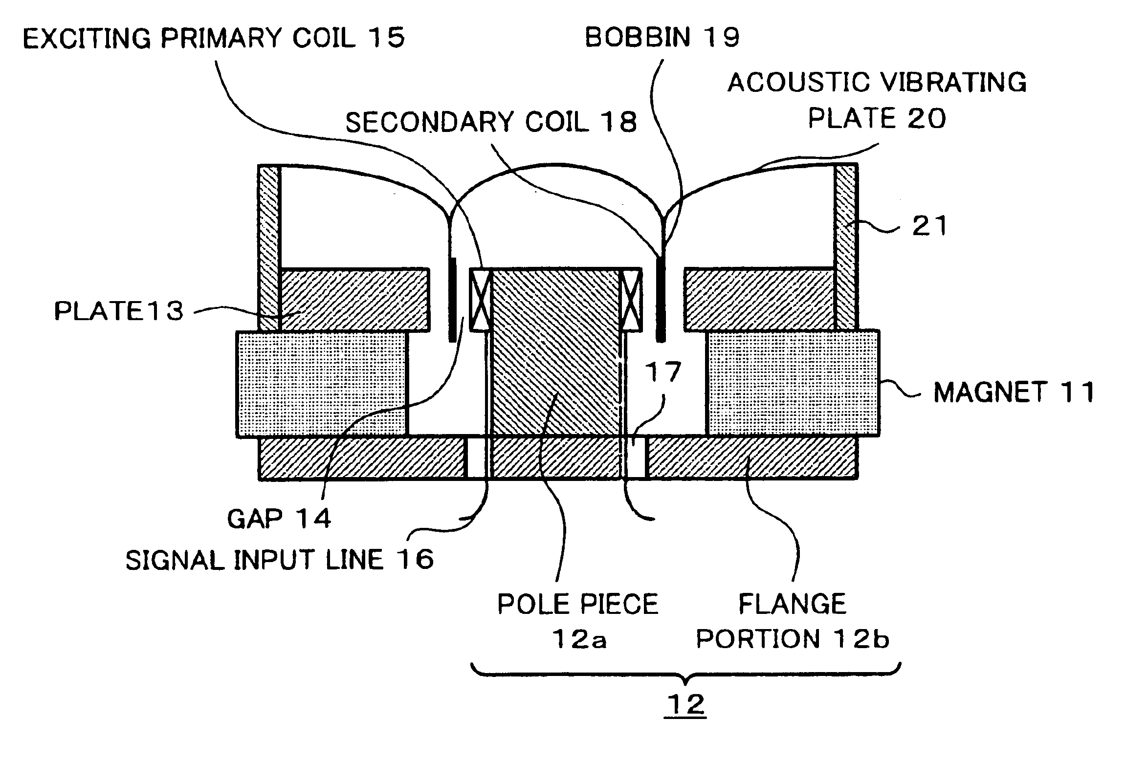
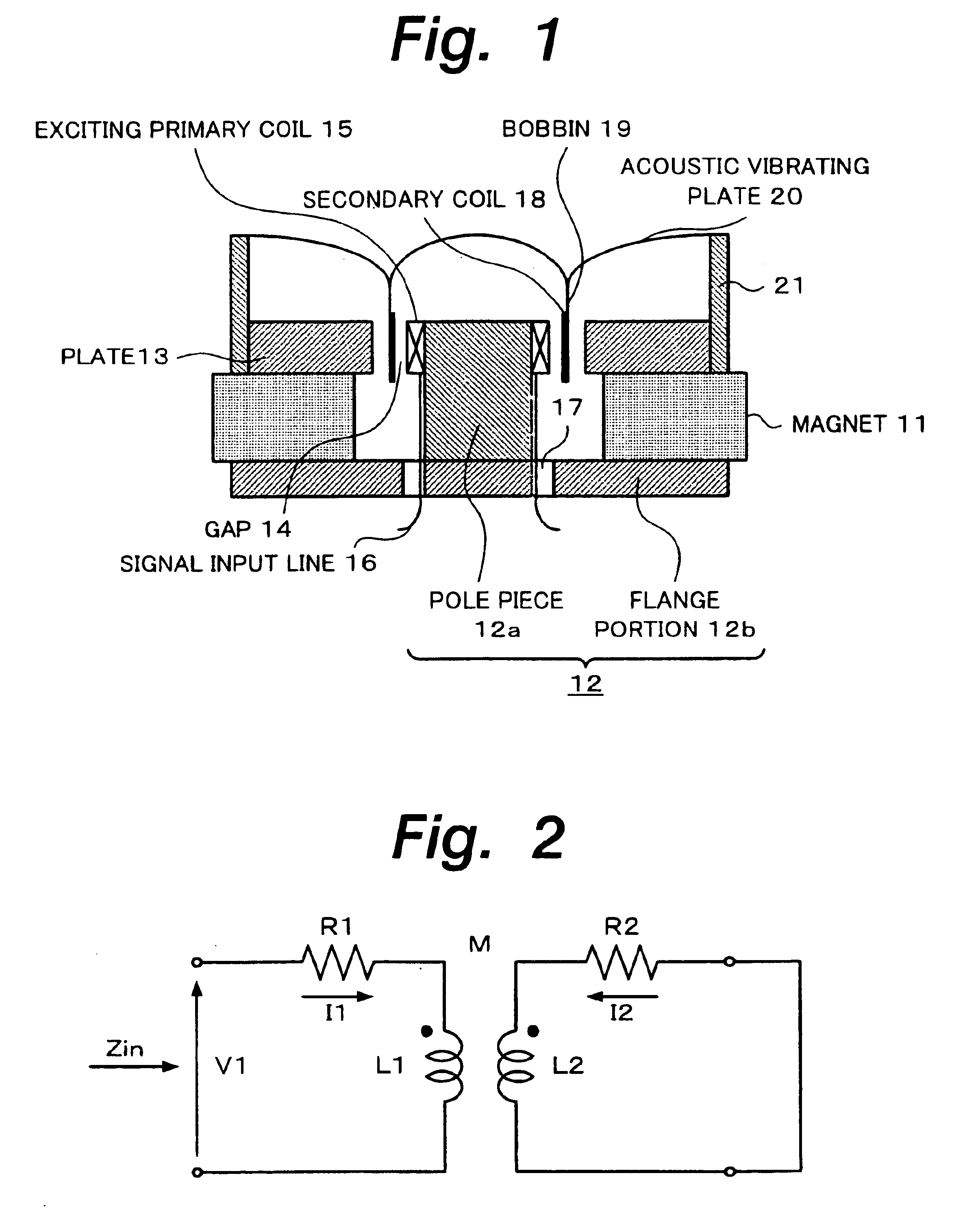
[0061]Next, an exciting primary coil 15 and a secondary coil 18 of a speaker apparatus according to a first embodiment based on the first mode of the present invention will be described.

[0062]In the first embodiment, the sizes and characteristics of the exciting primary coil 15 and the one-turn ring as the secondary coil 18 are as follows:

[0063]Exciting primary coil 15:

[0064]Diameter=13 mm; winding width=2.6 mm; number of winding layers=2; total number of turns (N)=33; DC resistance (R1)=3.22 Ω; inductance (L1)=34.5 μH

[0065]Secondary coil 18 (one-turn ring):

[0066]Diameter (inner diameter) 13.36 mm; width=3.0 mm; thickness=0.2 mm; material=aluminum; DC resistance (R2)=0.00207 Ω; inductance (L2)=0.032 μH

[0067]In this case, the inductance L2 is almost equal to L1 / N2.

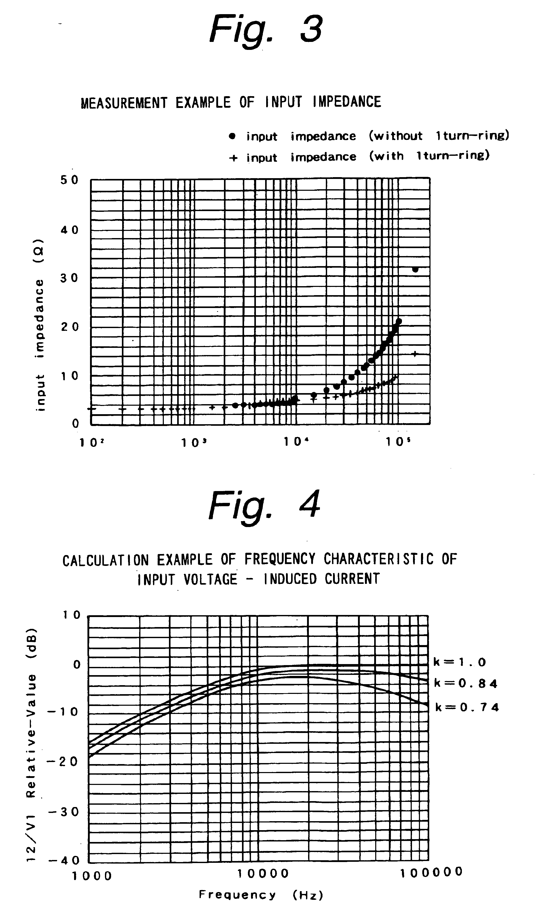
[0068]FIG. 3 shows a measurement example of the frequency characteristic of input impedance of the speaker apparatus according to the first embodiment. In FIG. 3, “·” represents a measurement point of the frequency characte...

second embodiment

[0074]Next, an exciting primary coil 15 and a secondary coil 18 of a speaker apparatus according to a second embodiment based on the second mode of the present invention will be described.

[0075]In the second embodiment, the characteristics of the exciting primary coil 15 and the one-turn ring as the secondary coil 18 are as follows. The frequency characteristic of the driving force is calculated corresponding to the amount of the induced current. In this example, the inductance L2 of the secondary coil 18 that is a one-turn conductive ring is a parameter. The coupling coefficient k is 0.9. The driving voltage V1 is 4 V. The magnetic flux density of the magnetic circuit is 1.5 T. The length of the one-turn conductive ring is 0.042 m.

[0076]Exciting primary coil 15:

[0077]DC resistance (R1)=3.22 Ω

[0078]Inductance (L1)=34.5 μH

[0079]Secondary coil 18 (one-turn conductive ring):

[0080]DC resistance (R2)=0.00207 Ω

[0081]Inductance (L2)=parameter

[0082]FIG. 5 shows the calculation result. Thus,...


PUM


Abstract

In an electromagnetic induction type speaker apparatus, individual constants are set in such a manner that the following formula is satisfiedN×(R1×R2)1 / 2 / {2 Π×L1×(1−k2)1 / 2}≧20000where R1 is the DC resistance of a primary coil 15: L1 is the inductance of the primary coil 15; N is the number of turns of the primary coil 15; R2 is the DC resistance of the secondary coil 18; L2 is the inductance of the secondary coil 18; and k is the coupling coefficient of the primary coil 15 and the secondary coil 18. In addition, the constants L1 and L2 are selected in such a manner that the ratio of the inductance L1 and the inductance L2 becomes equal to in the ratio of the DC resistance R1 and the DC resistance R2.

Description

TECHNICAL FIELD[0001]The present invention relates to a speaker apparatus for use with various audio units and video units.RELATED ART[0002]A conventional speaker apparatus is structured as shown in FIG. 6. Such a speaker apparatus is referred to as dynamic speaker. The speaker apparatus has a magnetic circuit that comprises a doughnut shaped magnet 1, a first magnetic yoke 2, a second magnetic yoke 3, and a gap 4. The first and second magnetic yokes 2 and 3 are composed of a magnetic material such as steel. The first magnetic yoke 2 is composed of a cylindrical pole piece 2a and a disc shaped flange portion 2b . The disc shaped flange portion 2b is perpendicular to the center pole portion 2a . The second magnetic yoke 3 is referred to as plate. The second magnetic yoke 3 is doughnut shaped in such a manner that the inner diameter of the second magnetic yoke 3 is larger than the outer peripheral diameter of the pole piece 2a by the gap 4.[0003]The magnet 1 is adhered to the front su...

Claims


Application Information

Patent Timeline
Patent Type & Authority Patents(United States)
IPC IPC(8): H04R9/04H04R9/00
CPCH04R9/046H04R2209/043
Inventor OHASHI, YOSHIO
Owner SONY CORP
Why Eureka
Try Eureka