This helps you quickly interpret patents by identifying the three key elements:
Problems solved by technology
Method used
Benefits of technology
Benefits of technology
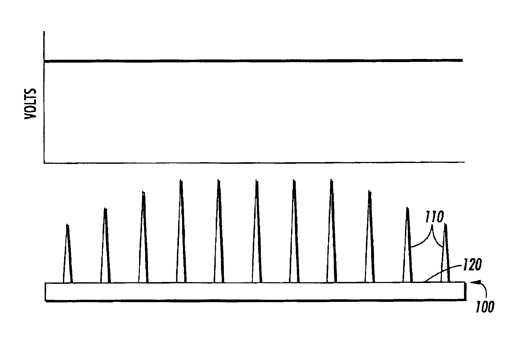
[0005]This effect can be understood from the symmetry and shielding of electric field by neighboring elements. The elements that lie inside the array have symmetrical flow of corona current on both sides, but the elements that lie near the edges have corona current only on one side of the pins. The electric field at the heads of inside elements, therefore, is reduced. As the voltage applied to the array is rai
Problems solved by technology
As illustrated by these FIGS. and by the disclosures of the references mentioned above, current design of saw tooth and pin array based corona producing devices are prone to non-uniform charging patterns.
Referring to the pins and teeth of such devices a
Method used
Image
Click on the blue label to locate the original text in one second.
Reading with bidirectional positioning of images and text.
Examples
Example
[0016]While exemplary embodiments will be described, there is no intent to limit the invention to the embodiments described. On the contrary, the intent is to cover all alternatives, modifications, and equivalents as may be included within the spirit and scope of the invention as defined by the appended claims.
DESCRIPTION
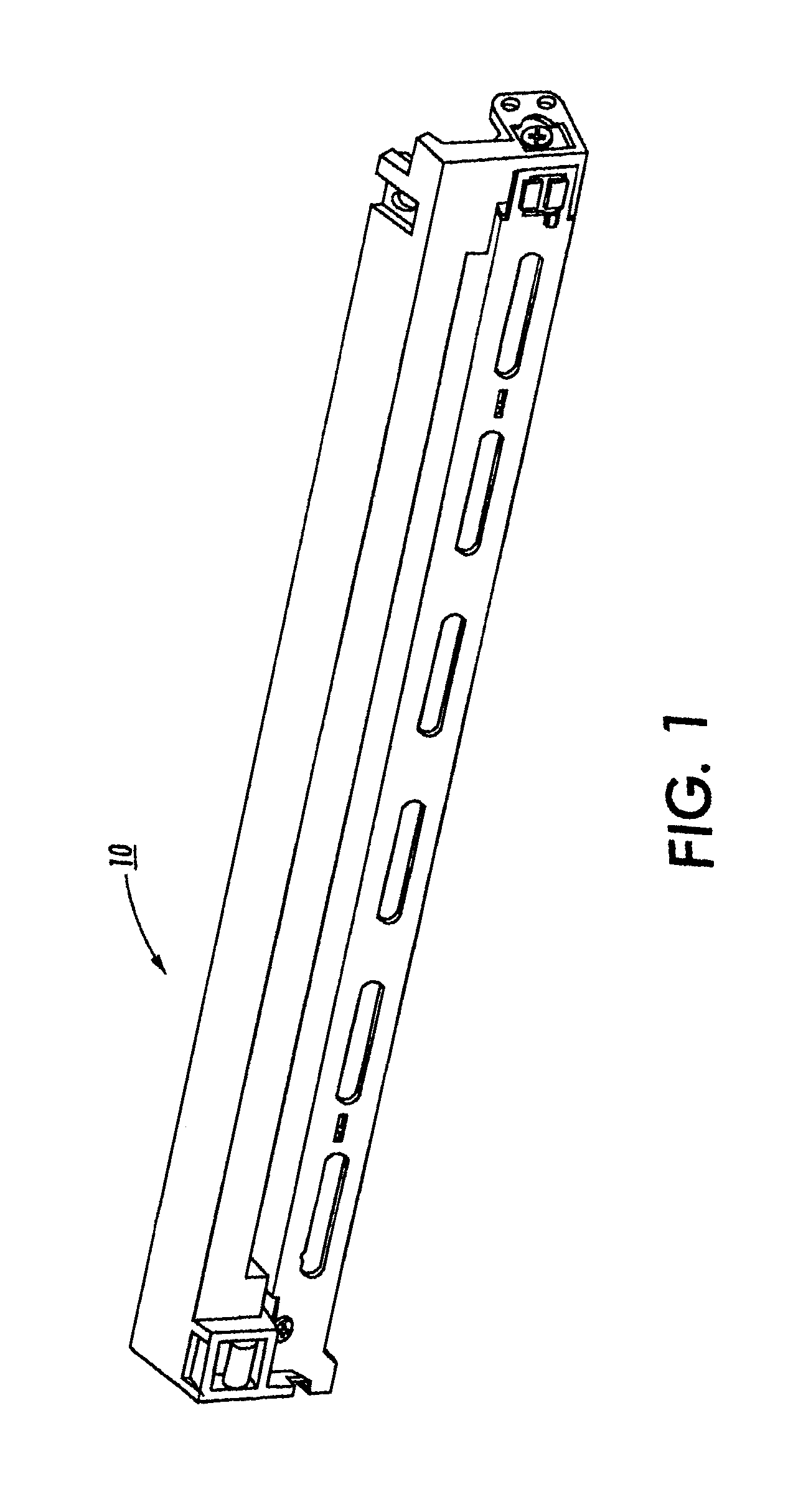
[0017]For a general understanding of the present invention, reference is made to the drawings. In the drawings, like reference numerals have been used throughout to designate identical elements. FIG. 1 shows a schematic elevational view of a charge device 10 including features of embodiments. Such a device is used in marking machines, such as a printer or photocopier (not shown), to charge a photoresponsive belt (not shown). The charge device can be, for example, a scorotron. From the outside, embodiments appear similar to the prior art.
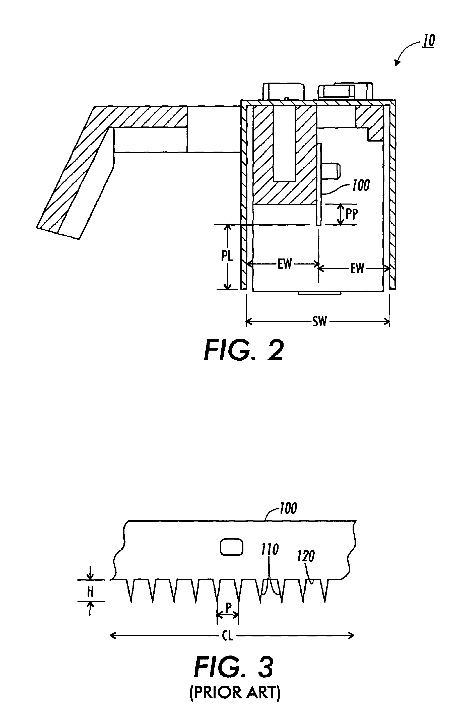
[0018]Referring particularly now to FIGS. 2-4, the housing supports a charge producing array 100 that is connected to a power sourc...
PUM
Abstract
By varying corona producing element height/projection, a more uniform charge potential is achieved. Elements, such as pins or teeth, are shorter at the edges of an element array and grow longer as one moves toward the center of the array. Such variation in height/projection overcomes shielding from adjacent teeth, as well as other effects, to yield the more uniform charging potential.
Description
CROSS-REFERENCE TO RELATED APPLICATIONS[0001]This application is based on a Provisional Patent Application No. 60 / 407,215, filed Aug. 29, 2002.FIELD OF THE INVENTION[0002]The invention relates to corona producing apparatus.BACKGROUND AND SUMMARY[0003]Electroreprographic systems, and xerographic systems in particular, use corona producing devices to produce electric fields to, for example, charge retentive photoresponsive surfaces, such as photoreceptor belt or drum surfaces. Various types of such corona charge generating devices include wires, while others include pins or teeth. In all cases, charge uniformity is desirable, and various solutions have been presented to make the fields produced by corona charge generating devices more uniform. U.S. Pat. Nos. 5,324,942, 2,777,957, 2,965,754, 3,937,960, 4,112,299, 4,456,365, 4,638,397, and 5,025,155 disclose various prior art corona charge producing devices; the disclosures of these patents are incorporated by reference into the disclos...
Claims
Application Information
Patent Timeline
Application Date:The date an application was filed.
Publication Date:The date a patent or application was officially published.
First Publication Date:The earliest publication date of a patent with the same application number.
Issue Date:Publication date of the patent grant document.
PCT Entry Date:The Entry date of PCT National Phase.
Estimated Expiry Date:The statutory expiry date of a patent right according to the Patent Law, and it is the longest term of protection that the patent right can achieve without the termination of the patent right due to other reasons(Term extension factor has been taken into account ).
Invalid Date:Actual expiry date is based on effective date or publication date of legal transaction data of invalid patent.
IPC IPC(8): G03G15/02H02H1/00
CPCG03G15/02G03G2215/028
InventorMISHRA, SATCHIDANANDDOMM, EDWARD A.PROSSER, DENNIS J.NONKES, STEVEN P.POPOVIC, ZORAN D.

