Light-emitting device and illuminating device

Inactive Publication Date: 2010-03-04
KK TOSHIBA
View PDF18 Cites 51 Cited by
  • Summary
  • Abstract
  • Description
  • Claims
  • Application Information

AI Technical Summary

Benefits of technology

[0008]According to an aspect of the invention, there is provided a light-emitting device including: a first laser light source radiating a first light having a light axis; a first diffusion member provided along the light axis of the first light, the first diffusion member receiving the first light and generating a second light from the first light, the second light outgoing in a direction different from a direction of the light axis of the first light, the first diffusion member having a first part and a second part, an intensity of the first light in the first part being lower than that in the second part, a ratio of generating the second light from the first light in the first part being higher than that in the second part; and a first wavelength converter provided along the first diffusion member, the first wavelength converter absorbing the second light and emitting a third light having a different wavelength from the second light.
[0009]According to another aspect of the invention, there is provided an illumin

Problems solved by technology

However, in this method, because the light having different wavelengths is used as the light source, unevenness of the color is caused while the light is propagated through the light guide plate.
That is, the light such as white light in which components having d

Method used


Image

  • Light-emitting device and illuminating device
  • Light-emitting device and illuminating device
  • Light-emitting device and illuminating device

Examples


Example

First Embodiment

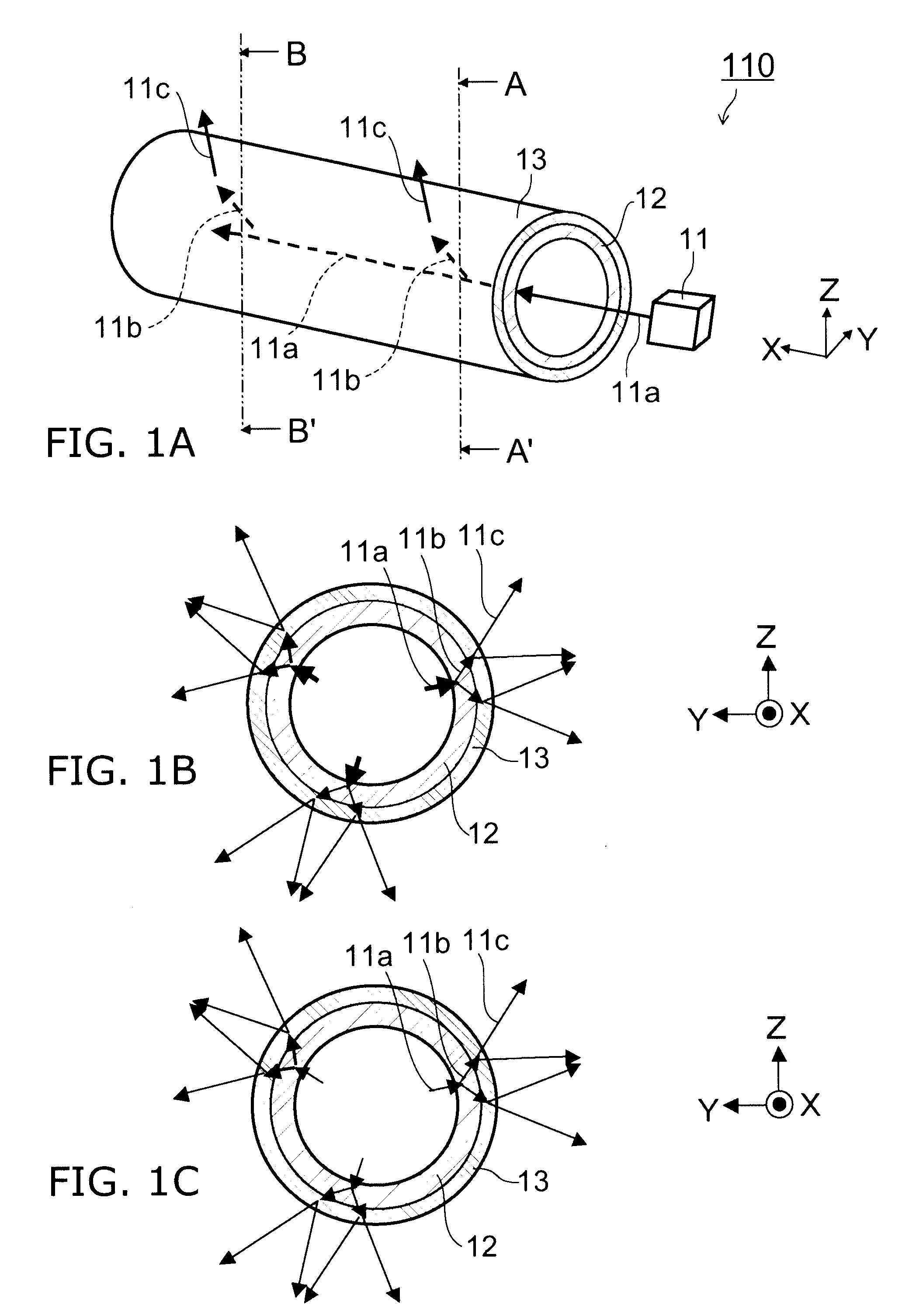
[0036]FIGS. 1A to 1C are schematic views illustrating the configuration of a light-emitting device according to a first embodiment of the invention.

[0037]That is, FIG. 1A is a schematic perspective view, and FIG. 1B is a cross-sectional view taken along line A-A′ of FIG. 1A, and FIG. 1C is a cross-sectional view taken along line B-B′.

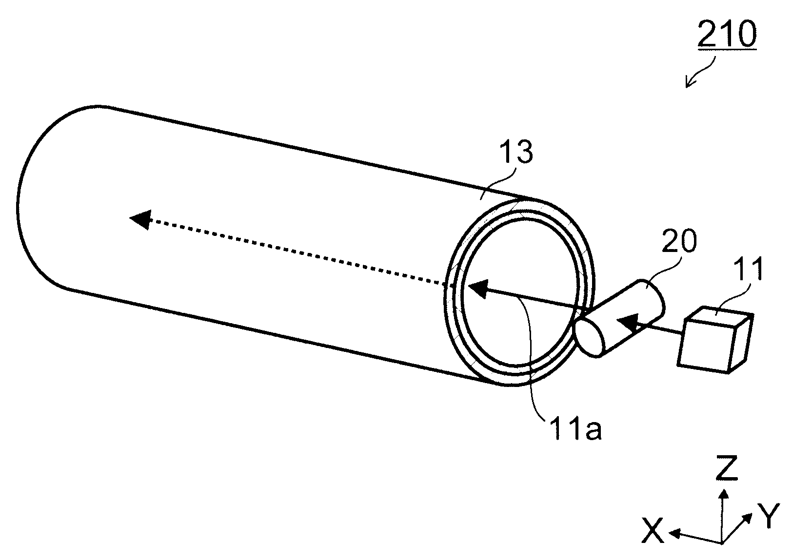
[0038]As shown in FIG. 1A, the light-emitting device 110 according to the first embodiment of the invention includes a first laser light source 11, a first diffusion member 12 provided along a light axis of a first light 11a radiated from the first laser light source 11 and generating from the first light 11a a second light 11b outgoing in different directions from the light axis direction of the first light 11a, and a first wavelength-converter 13 provided along the first diffusion member 12, absorbing the second light 11b and emitting a third light having a different wavelength from the second light 11b.

[0039]And, in the first diffusi...

Example

Second Embodiment

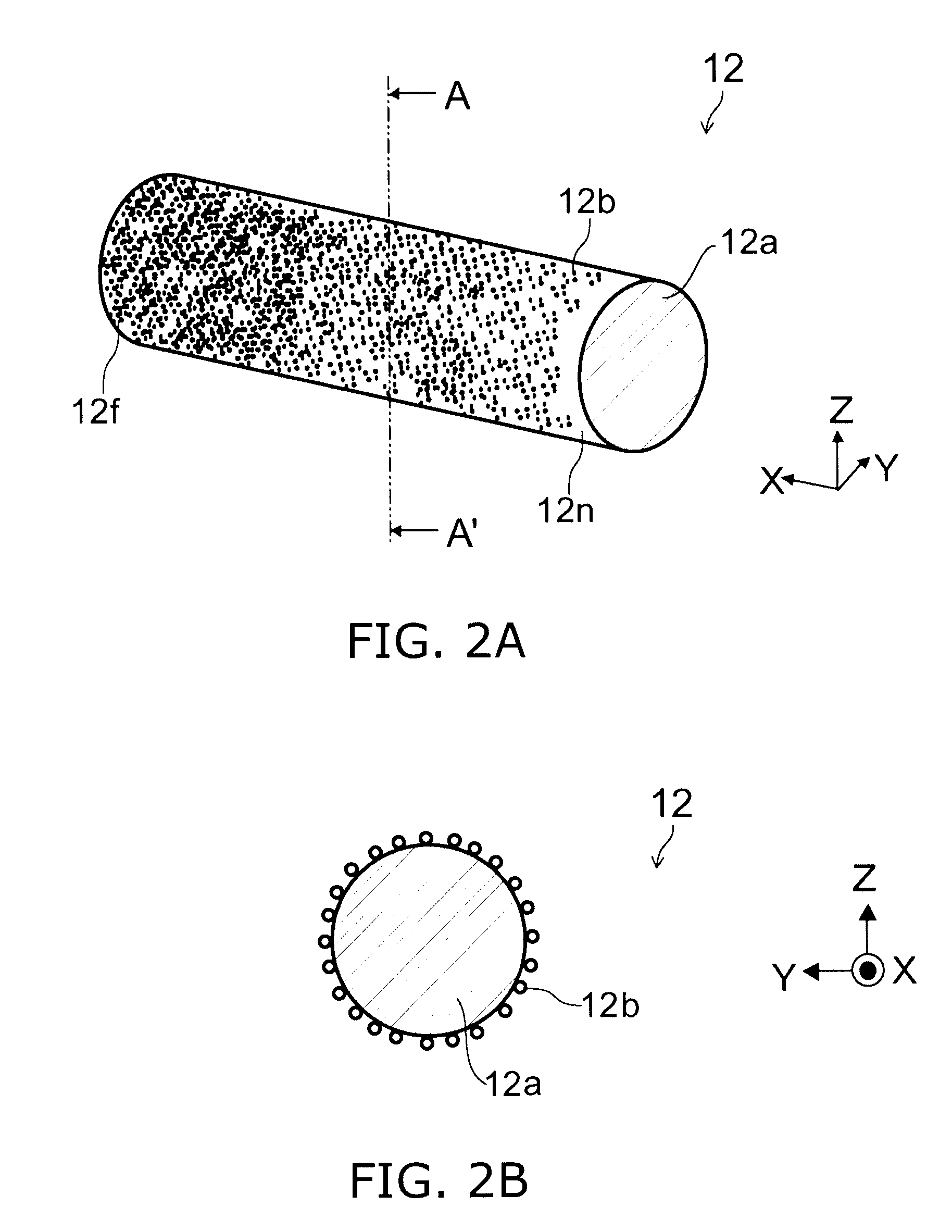
[0107]FIG. 4 is a schematic perspective view illustrating the configuration of a diffusion member used in the light-emitting device according to a second embodiment of the invention.

[0108]FIGS. 5A and 5B are graphs illustrating characteristics of a diffusion member used in the light-emitting device according to the second embodiment of the invention.

[0109]That is, the vertical axis of FIGS. 5A and 5B represents density C of the diffusion bodies 12b. And, the horizontal axis of the FIG. 5A represents distance x in the X axis direction, and the horizontal axis of FIG. 5B represents distance y in the Y axis direction. The horizontal axis of FIG. 5B may be distance z in the Z axis direction.

[0110]The light-emitting device 120 according to the second embodiment has characteristics in the first diffusion member 12, and thus, the first diffusion member 12 will be described.

[0111]As shown in FIG. 4, in the light-emitting device 120 according to the second embodiment, the fi...

Example

Third Embodiment

[0119]FIG. 6 is a schematic perspective view illustrating the configuration of a diffusion member used in the light-emitting device according to a third embodiment of the invention.

[0120]FIGS. 7A and 7B are graphic views illustrating characteristics of a diffusion member used in the light-emitting device according to the third embodiment of the invention.

[0121]That is, the horizontal axis of FIGS. 7A and 7B represents distance x in the X axis direction. And, the vertical axis of the FIG. 7A represents particle diameter d of the diffusion bodies 12b, and the vertical axis of FIG. 7B represents difference (absolute value of difference) Δd between the particle diameter d of the diffusion bodies 12b and the wavelength of the first light 11a.

[0122]The light-emitting device 130 according to the third embodiment has characteristics in the first diffusion member 12, and therefore, the first diffusion member 12 will be described.

[0123]As shown in FIG. 6, in the light-emittin...


PUM


Abstract

A light-emitting device includes: a first laser light source; a first diffusion member provided along a light axis of a first light radiated form the first laser light source; and a first wavelength converter provided along the first diffusion member. The first diffusion member generates a second light from the first light. The second light outgoes in a direction different from the light axis direction of the first light. A ratio of generating the second light from the first light in a first part is higher than that in a second part, wherein an intensity of the first light in the first part is lower than that in a second part. The first wavelength converter absorbs the second light and emitting a third light having a different wavelength from the second light.

Description

CROSS-REFERENCE TO RELATED APPLICATIONS[0001]This application is based upon and claims the benefit of priority from the prior Japanese Patent Application No. 2008-221592, filed on Aug. 29, 2008; the entire contents of which are incorporated herein by reference.BACKGROUND OF THE INVENTION[0002]This invention relates to a light-emitting device and an illuminating device.BACKGROUND ART[0003]A Light emitting device having, for example, a plane shape or a line shape and generating, for example, white light by using a light-emitting element such as LED (Light Emitting Diode) has been developed, and is applied to, for example, back light of a liquid crystal display apparatus, or the like.[0004]By contrast, if a light emitting device having a line shape or a rod shape, for example, a shape such as a fluorescent lamp can be realized from a light source having a small area by a laser light-emitting element, a higher efficient illuminating device can be realized.[0005]However, in the laser lig...

Claims


Application Information

Patent Timeline
IPC IPC(8): G02B27/20G02F1/35
CPCG02B6/001G02B6/0096G02F2201/02G02F1/133609G02F2001/133614G02F1/133603G02B6/023G02F1/133614
Inventor SATO, TAKAHIROSAITO, SHINJINUNOUE, SHINYAHATTORI, YASUSHISUGAI, MAKI
Owner KK TOSHIBA
Why Eureka
Try Eureka