Spectroscopic detector and method for determining the presence of blood and biological marker substances in liquids

Active Publication Date: 2009-11-12
FRESENIUS MEDICAL CARE DEUTSCHLAND GMBH
View PDF22 Cites 5 Cited by
  • Summary
  • Abstract
  • Description
  • Claims
  • Application Information

AI Technical Summary

Benefits of technology

[0033]According to a further embodiment, air recognition in an optically dense solution is also possible. If air enters the secondary circuit tube, this lowers the intensity of the spectrum measured. This is because ai

Problems solved by technology

However, optical transmission measurements are not possible

Method used


Image

  • Spectroscopic detector and method for determining the presence of blood and biological marker substances in liquids
  • Spectroscopic detector and method for determining the presence of blood and biological marker substances in liquids
  • Spectroscopic detector and method for determining the presence of blood and biological marker substances in liquids

Examples


Example

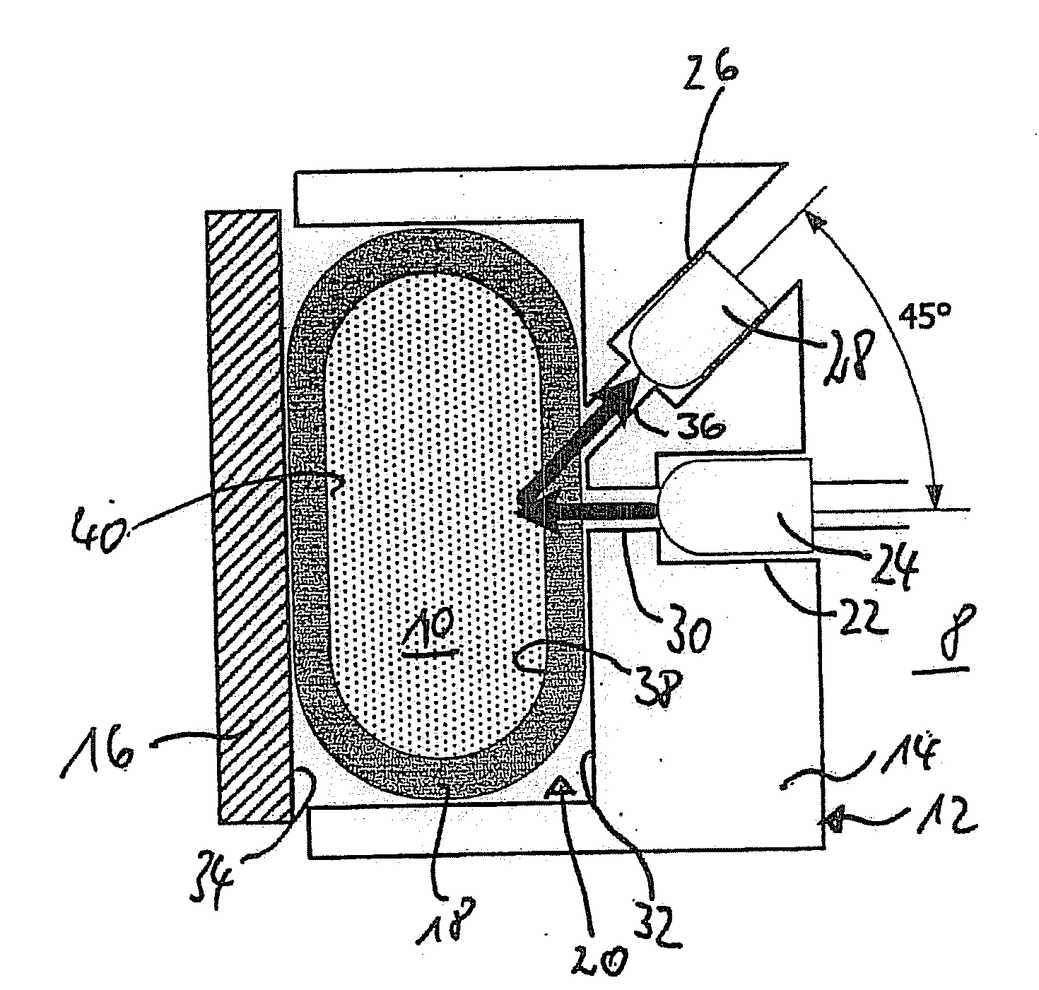
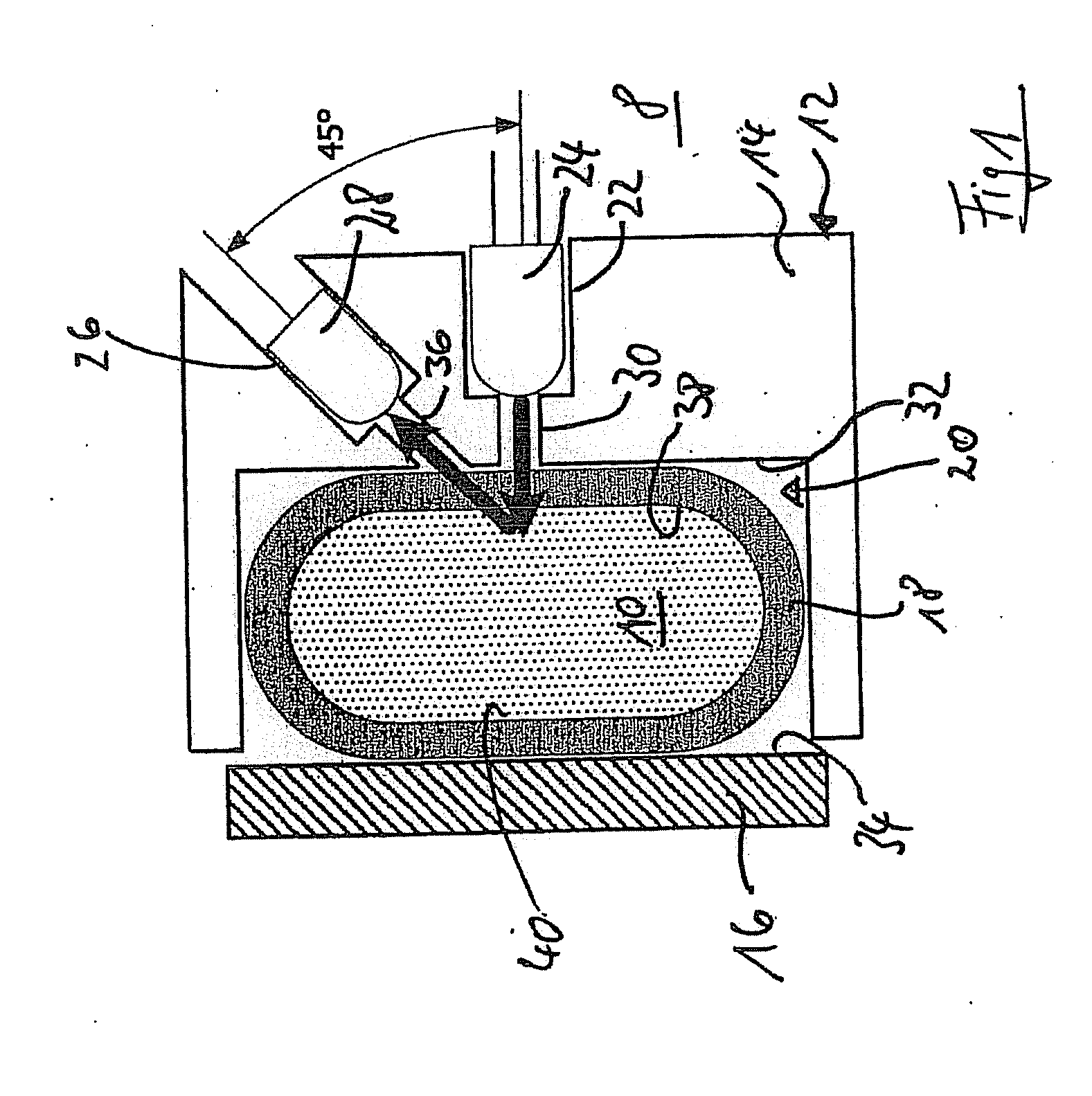
[0049]FIG. 1 shows a first embodiment of the detector 8 according to the invention in a view diagonal to the flow direction of the liquid 10. A casing 12 is formed by a main casing part 14 and a casing lid 16, which serves for simple insertion of a tube 18 into the casing 12 and as a measuring background. When tube 18 is inserted, the casing lid 16 is fastened with tightly sealing effect on the main casing part 14.

[0050]The main casing part 14 further comprises a channel 20 for guiding tube 18 through casing 12, a first recess 22 for mounting a light emitter 24 and a second recess 26 for mounting a light detector 28. Both recesses 22 and 26 open from the outside of the main casing part 14 and extend over a narrowed first shutter 30 for the ray beam of light emitter 24 and a second narrowed shutter 36 for the ray beam of light detector 28 and then through the main casing part 14 to end in the channel 20.

[0051]The light emitter 24 is advantageously a light source emitting white light,...

Example

[0059]FIG. 3a shows a second embodiment of the detector 8 in cross-section in a measurement in optically dense solution. In contrast to the embodiment shown in FIGS. 1 and 2, a glass pane 46 which is permeable to the irradiated light is arranged between the first tube wall 38 and the surface 32. This prevents possible contaminations of the light emitter or light detector openings in the casing 12. The rear casing wall 34 is advantageously arranged parallel to the glass pane 46.

[0060]FIG. 3b shows a further embodiment with two light emitters of different irradiation wavelengths (e.g. green). In addition to the first light emitter 24, there is a second light emitter 48, which is mounted in a third recess 50 in the main casing part 14. The recess 50 opens from the outside of the main casing part 14 and extends over a further narrowed third shutter 52 for the ray beam of the light emitter 48 through the main casing part 14 and also ends in channel 20. The light beam and the optical axis...


PUM


Abstract

The invention relates to a detector for measuring scattered light in liquids having a housing, a transparent, flexible tube for transporting liquid through the housing, a light emitter, and a light detector. Two parallel surfaces are formed in the housing, between which the tube is arranged such that two opposing tube walls are formed in a planar parallel manner. The light emitter is arranged in such a way that the optical axis thereof is perpendicular to the parallel surfaces of the first tube wall, and the light detector is adjacent to the light emitter, the optical axes of the light emitter and light detector forming an angle smaller than 90°. The invention also relates to a method for detecting the presence of blood and for the quantitative determination of biological marker substances, especially bilirubin, in solution, and to a device for treating blood containing the detector.

Description

CROSS REFERENCE TO RELATED APPLICATIONS[0001]This is a 371 national phase application of PCT / EP2007 / 000433 filed Jun. 26, 2007, claiming priority to German Patent Application No. 10 2006 029 899.3 filed Jun. 29, 2006.FIELD OF INVENTION[0002]The invention concerns a detector and the detection of blood and biological marker substances in optically dense and clear liquids or in secondary liquids used in blood purification machines.BACKGROUND OF THE INVENTION[0003]To ensure patient safety, a blood detector must be used when using a membrane filter for blood purification to prevent critical patient conditions caused by risks such as possible blood loss, membrane rupture of the filter, mistaking of connections or hemolysis.[0004]Spectroscopic analyses for determining blood and biological marker substances in solution are known from the prior art. EP 0 575 712 A2 describes the spectroscopic analysis of blood on a squeezed tube in dialysis and measurement in transmission. EP 1 083 948 B1 de...

Claims


Application Information

Patent Timeline
IPC IPC(8): G01N33/49G01N33/00
CPCA61B5/14557A61M1/1692G01N21/85G01N21/534G01N21/53G01N2021/0364
Inventor BADO, ITKAHERRENBAUER, MICHAELMOISSL, ULRICH
Owner FRESENIUS MEDICAL CARE DEUTSCHLAND GMBH
Why Eureka
Try Eureka