

Adaptive glint reduction method and system
a glint reduction and glint technology, applied in the field of angular noise reduction methods and systems, can solve the problems of general use of radar tracking systems, complex shape, and change in total return signals with time, so as to improve tracking of targets and reduce correlation errors
- Summary
- Abstract
- Description
- Claims
- Application Information
AI Technical Summary
Benefits of technology
Problems solved by technology
Method used
Image

Examples
Embodiment Construction
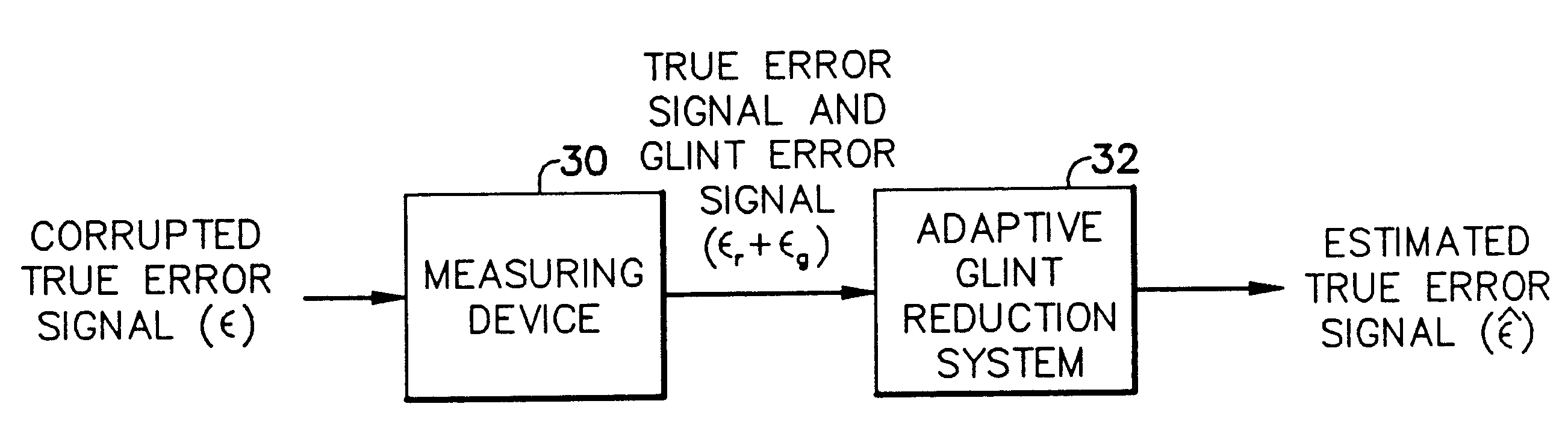
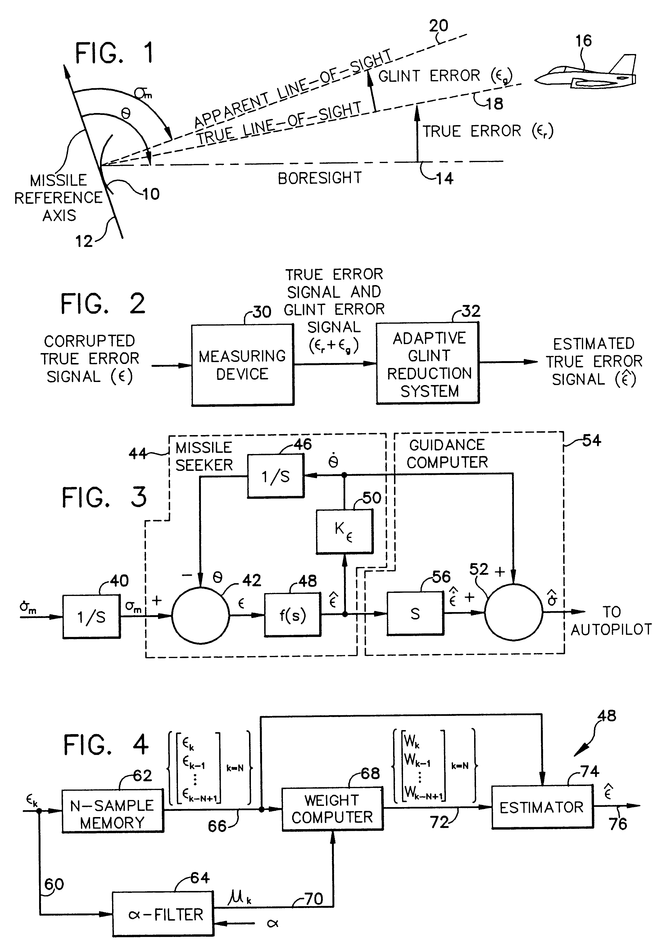
[0023]FIG. 1 is a diagramatic illustration of the relationship between a missile reference axis, the missile radar system antenna boresight and the apparent and true lines of sight to a target. In FIG. 1 a missile radar antenna 10 is typically gimble mounted upon a missile (not shown) having a reference axis 12. Antenna 10 has an electrical boresight axis which is illustrated in FIG. 1 by the broken line identified by reference numeral 14. A true line of sight from antenna 10 to target 16 is indicated by the dashed lines identified by reference numeral 18. The angular displacement between antenna boresight 14 and the true line of sight 18 is generally defined as the true angular error εr.
[0024]In an ideal radar system, the radar signals reflected from target 16 would result in the measurement of only the true angular error εr between the antenna boresight 14 and the true line of sight 18 to target 16. In actuality, angular noise or glint is developed in the radar beam when reflected...
PUM
 Abstract
Description
Claims
Application Information