High speed phase locked loop

a phase lock and high-speed technology, applied in the field of phase lock loops, can solve the problems that the prescaler architecture and the dual-modulus prescaler architecture cannot enable the maximum potential frequency limit of operation, and achieve the effect of reducing the signal amplitude of the differential d flip-flop and the highest operating frequency

a phase lock and high-speed technology, applied in the field of phase lock loops, can solve the problems that the prescaler architecture and the dual-modulus prescaler architecture cannot enable the maximum potential frequency limit of operation, and achieve the effect of reducing the signal amplitude of the differential d flip-flop and the highest operating frequency

US6940322B2Inactive Publication Date: 2005-09-06UNIV OF FLORIDA RES FOUNDATION INC

Image

  • High speed phase locked loop
  • High speed phase locked loop
  • High speed phase locked loop

Examples


Embodiment Construction

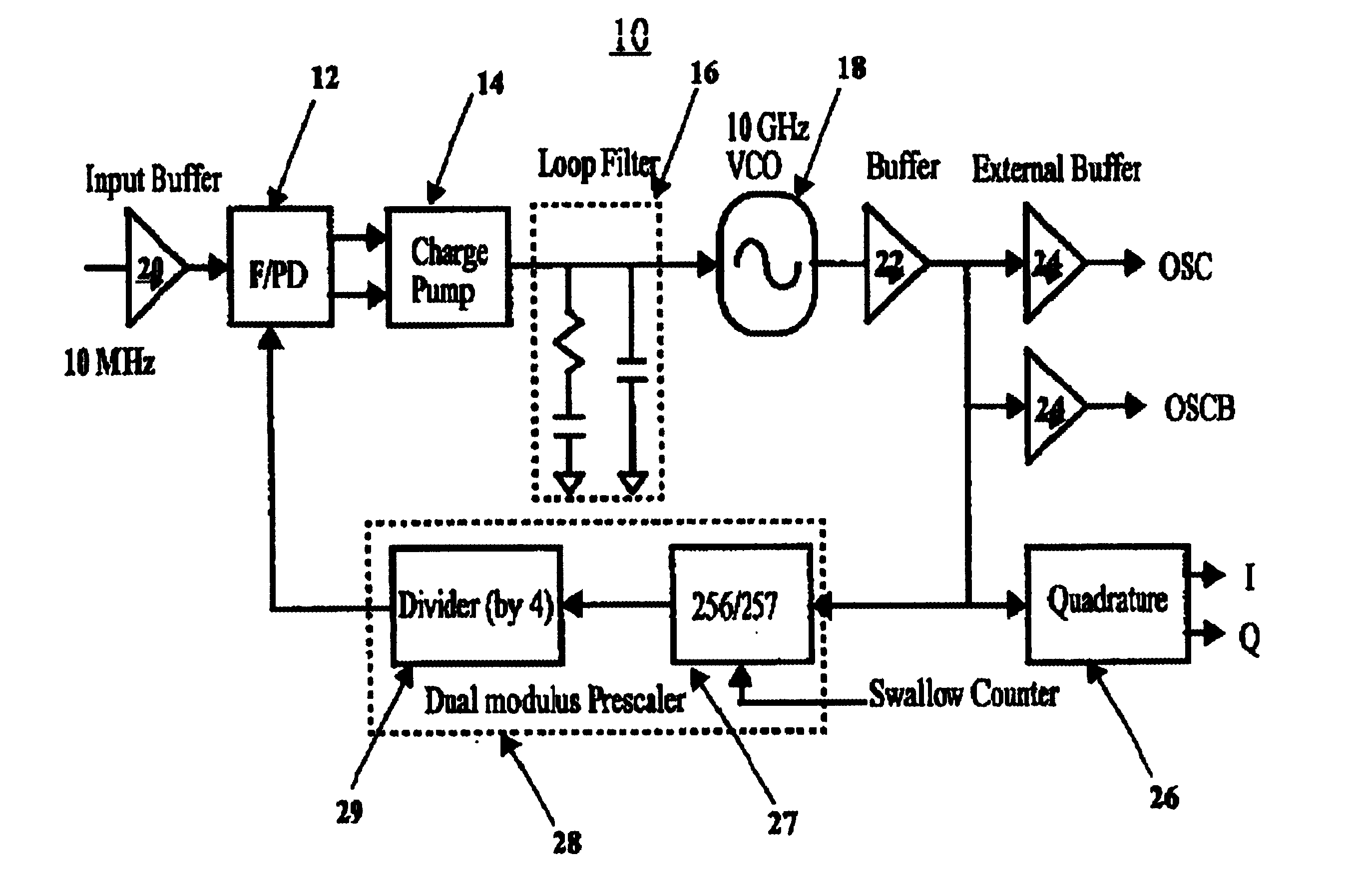
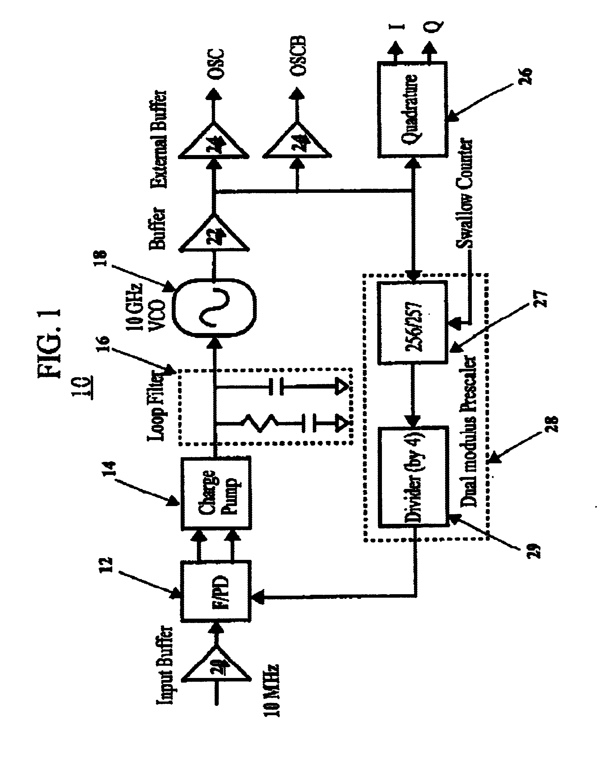
[0018]Embodiments in accordance with the invention as shown in FIG. 1 can include a PLL 10 such as a 10.4-GHz PLL with a dual modulus prescaler 28 such as a 256 / 257 dual modulus prescaler implemented in a 0.18-μm CMOS process. The prescaler 28 can include a divider or counter 29 such as a 4 / 5 synchronous counter that can operate up to 14 GHz and potentially higher. The counter 29 achieves this by using feedback. The phase noise levels of the PLL and VCO at a 3-MHz offset with Ivco=8.1 mA are −122 dBc / Hz as shown in FIG. 5. The PLL 10 can operate between 9.7 and 10.4 GHz, while drawing a low current of less than 35 mA at VDD=1.8V, such as 34 mA.

[0019]Referring again to FIG. 1, the PLL 10 can include a voltage controlled oscillator (VCO) 18, a VCO buffer 22, a 256 / 257 dual modulus prescaler 28, a divider (divide by 4) 29, a phase frequency detector (FPD) 12, a charge pump 14 and a loop filter 16. The FPD 12 and charge pump 14 can use a 3 state phase detection scheme as further detaile...


PUM


Abstract

A high speed CMOS phase locked loop (PLL) (10) includes a three-state phase detection circuit having a frequency phase detector (12) coupled to a charge pump (14) for monitoring the phase differences between a reference frequency signal and a divided output frequency signal. The PLL can further include a loop filter (16)coupled to the three-state phase detection circuit, a VCO (18) coupled to the output of the loop filter, a VCO buffer (22) coupled to the output of the VCO for providing an output frequency signal, and a dual modulus prescaler (28) having a synchronous counter (27 and 29) using feedback among D flip-flops (30 and 32) for generating the divided output frequency signal.

Description

BACKGROUND OF THE INVENTION[0001]1. Technical Field[0002]This invention relates to the field of phase locked loops and more particularly to high speed phase locked loops (PLLs).[0003]2. Description of the Related Art[0004]A phase locked loop typically has three core components, namely, a phase detector or multiplier, a loop filter and a voltage controlled oscillator (VCO). PLLs can also include a prescaler. For a given technology, a PLL dual modulus prescaler usually sets the upper limit on the maximum operating frequency. Existing PLL architectures and dual-modulus prescaler architectures fail to enable the maximum potential frequency limits of operation for the PLL and prescaler while also maintaining other desirable PLL performance parameters.[0005]A CMOS high-speed PLL would ideally include other characteristics that are not readily achievable with existing technology while operating at a maximum frequency. Namely, such PLL would ideally operate at a low voltage, draw a small cu...

Claims


Application Information

Patent Timeline
06 Sep 2005
Publication
US6940322B2
IPC
H03K3/354; H03K23/66; H03K3/00; H03K23/00; H03L7/193; H03L7/16
CPC
H03K3/354; H03K23/667; H03L7/193
Inventors
YANG, DONG-JUN; O, KENNETH