Switchable omni-directional antennas for wireless device

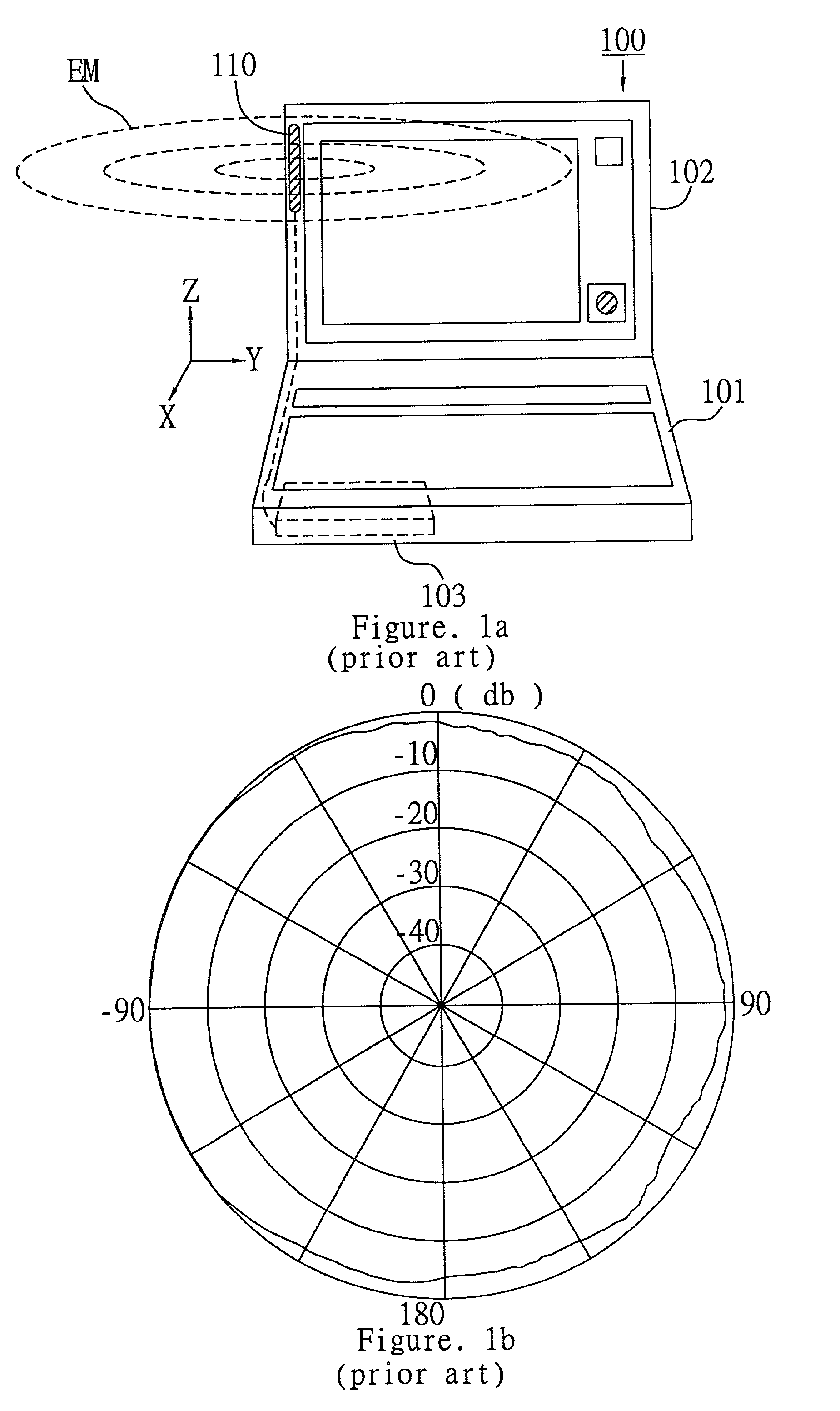
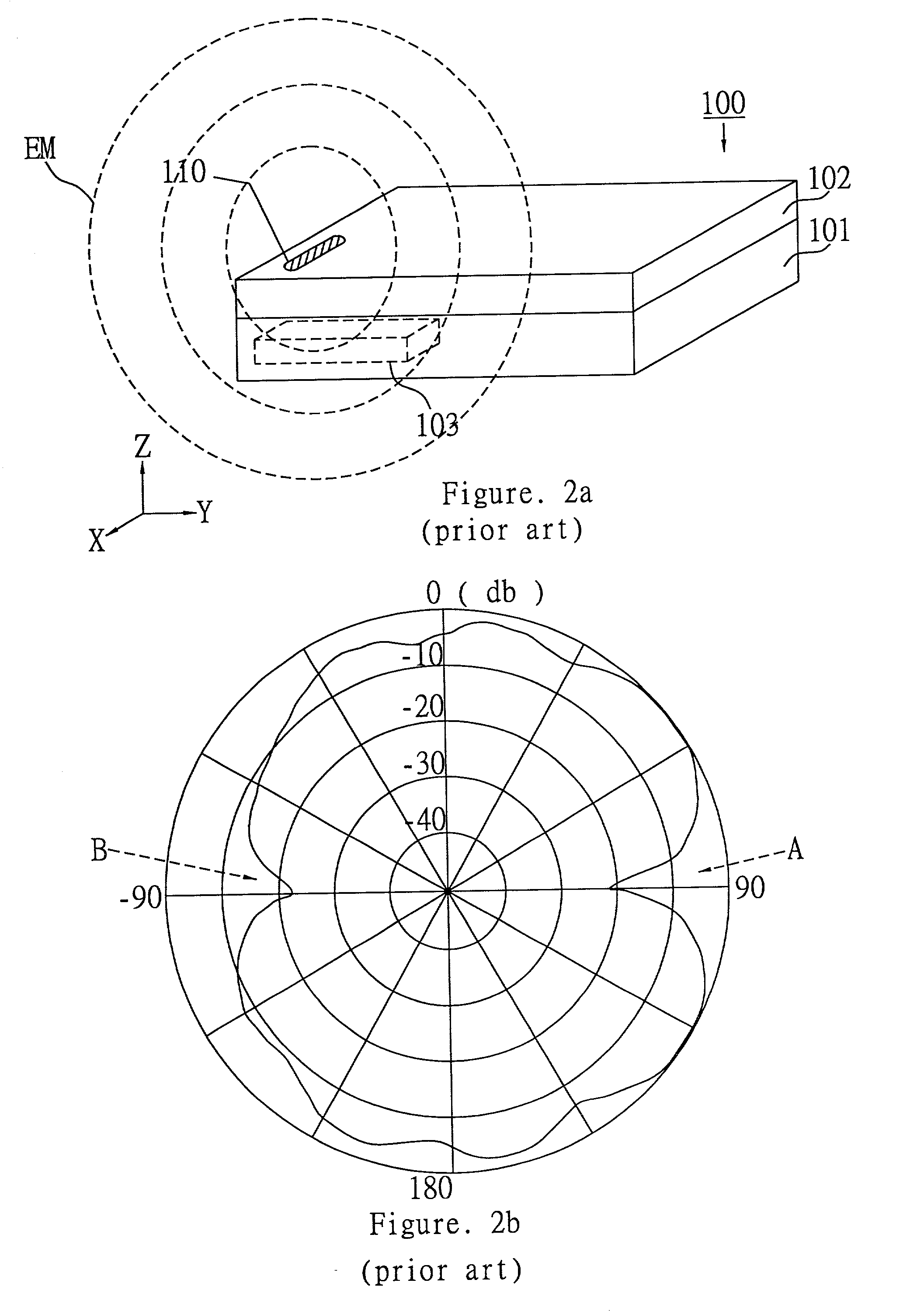
a wireless device and omni-directional technology, applied in the direction of instruments, portable computers, polarised antenna unit combinations, etc., can solve the problems of limiting transmission efficiency and gain, and not being able to provide an omni-directional horizontal radiation pattern

Active Publication Date: 2005-10-25
WISTRON NEWEB
View PDF7 Cites 31 Cited by
  • Summary
  • Abstract
  • Description
  • Claims
  • Application Information

AI Technical Summary

Benefits of technology

[0011]The present invention discloses an electronic device having the capability of wireless communication through two mutually switchable antennas mounted thereon. One of the antennas is omni-directional in the horizontal plane when the device is operating in its first state, while the other antenna is omni-directional in the horizontal plane when the device is operating in second operating state. The switching between the antennas is automatically or manually triggered in conjunction with transition from the first state to the second state and vice versa. The transition occurs as the device reorients itself, so do the antennas, during normal usage. The switching is to effect a selection from the antennas of one that is currently omni-directional in the horizontal plane, so that the device retains its transmission quality as its user changes the operating state. The present invention does not exclude any existing transmission protocol, and is particularly useful for movable wireless devices using Bluetooth or IEEE 802.11b.

Problems solved by technology

The prior art described has the disadvantage of not being able to provide an omni-directional horizontal radiation pattern when the mobile device, and hence the antenna itself mounted thereon, are being constantly reoriented in their possible operating states.
This would limit the transmission efficiency and gain.

Method used


Image

  • Switchable omni-directional antennas for wireless device
  • Switchable omni-directional antennas for wireless device
  • Switchable omni-directional antennas for wireless device

Examples


Embodiment Construction

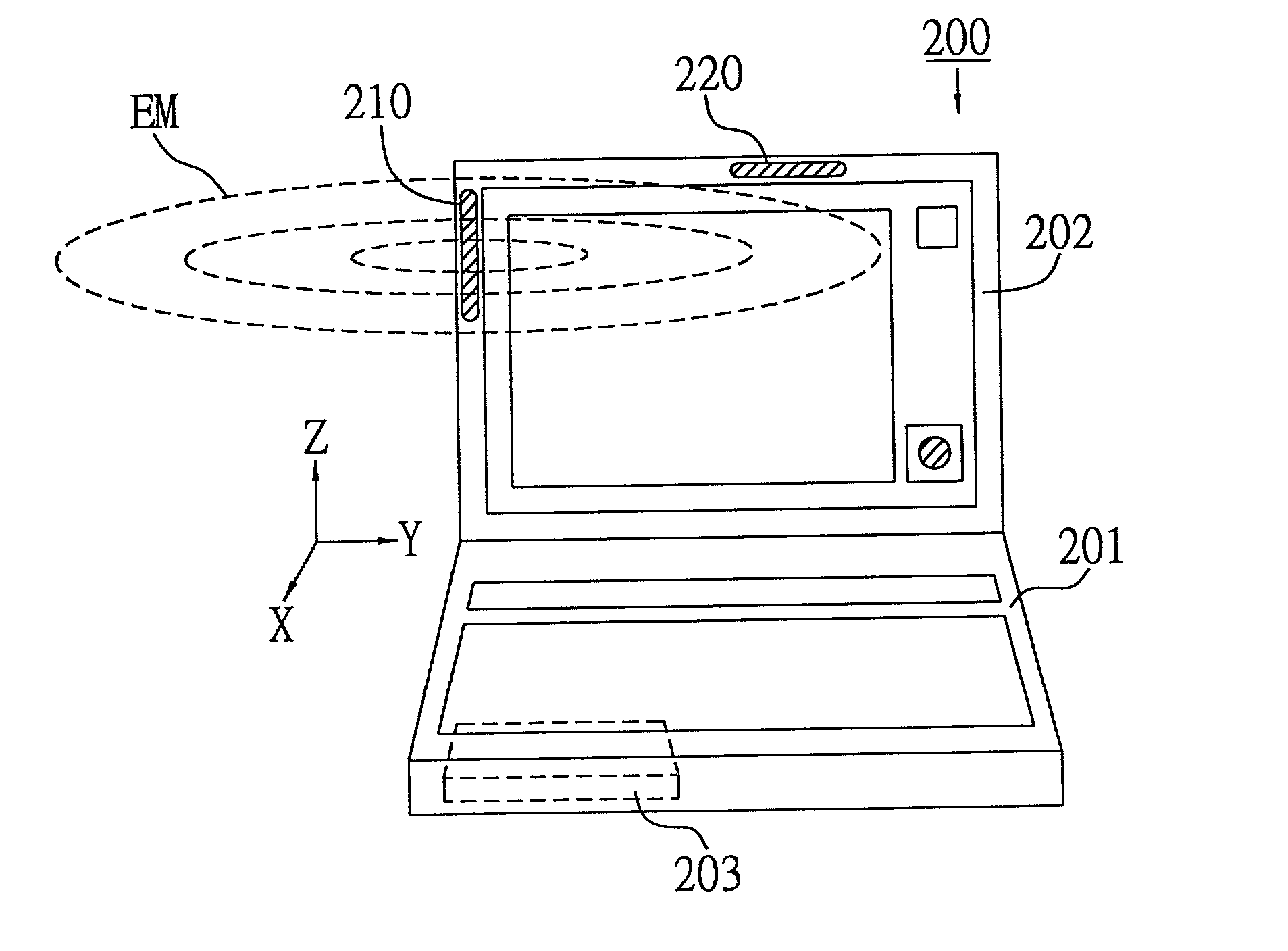
[0026]What follows is a detailed description of embodiments of the present invention for the purpose of fully disclosing the various features of the present invention and its improvements over the prior art in conformity with patent law. The present invention relates to a combination of antennas for an electronic device having different operating states. The antennas are mutually switchable, and for each of the operating state of the device an omni-directional radiation pattern in the horizontal plane will be generated by switching between the antennas. The present invention is conceptual and can be applied to each and every wireless transmission standard and protocol.

[0027]FIG. 3 and FIG. 4 illustrate one embodiment of the present invention wherein two switchable omni-directional antennas are installed in a notebook computer. The omni-directional antennas 210 and 220 are mounted on the left side and top of the display panel 202 of the notebook computer 200, respectively, and are co...


PUM


Abstract

Disclosed is an electronic device having wireless communication functions via a pair of antennas. The device can function under two operating states, both with an omni-directional radiation pattern in the horizontal plane. This is accomplished by an antenna pair mounted separately thereon, the first antenna thereof being omni-directional in the horizontal plane when the device is operative under the first operating state, and the second antenna thereof being omni-directional in the horizontal plane when the device is operative under the second operating state. Also included in the device are a wireless communication module for encoding and decoding signals that are transmitted and received, respectively, during wireless communication through the antenna pair; a RF switch coupling the wireless communication module to the first antenna and second antenna for switching between the first antenna and second antenna; and a trigger switch for detecting the transition of the electronic device between the first operating state and second operating state that causes rotation in space of the antenna pair, and for triggering the RF switch in responsive thereto. The RF switch switches to the first antenna as the electronic device transitions to the first operating state, and the RF switch switches to the second antenna as the electronic device transitions to the second operating state.

Description

REFERENCE TO RELATED APPLICATIONS[0001]The present application claims priority to Taiwan application NO. 090113165 entitled “Switchable antenna device with omni-directional radiation pattern and apparatus incorporating the same” filed on 31st May 2001.BACKGROUND OF THE INVENTION[0002]1. Field of the Invention[0003]The present invention relates to wireless communication technology. It more particularly relates to a wireless communication device that alters its operating mode in accordance with the operating state of an electronic apparatus whereto it is bundled for the purpose of maintaining an omni-directional radiation pattern. The present invention allows a more stable and reliable wireless transmission capability by ensuring that the antenna device always operates with best transmission quality even though the apparatus may vary its physical orientation when being operative. Obviously, the present invention is most suitable for portable wireless communication systems without fixe...

Claims


Application Information

Patent Timeline
Patent Type & Authority Patents(United States)
IPC IPC(8): H01Q21/24H01Q1/22H01Q21/26
CPCG06F1/1616G06F1/1677G06F1/1683G06F1/1698H01Q1/22H01Q1/2266H01Q21/24H01Q21/26
Inventor FANG, CHIEN-HSING
Owner WISTRON NEWEB
Why Eureka
Try Eureka