Hammer drill with a mechanism for preventing inadvertent hammer blows

a technology of hammer drill and mechanism, which is applied in the direction of drilling drives, drilling machines, manufacturing tools, etc., can solve the problems of delivering hammer blows to the tool bit, piston cylinder rotating, and not being free from certain problems and inconveniences, and achieve the effect of reliably preventing inadvertent blows

Inactive Publication Date: 2005-12-06
MAKITA CORP
View PDF14 Cites 54 Cited by
  • Summary
  • Abstract
  • Description
  • Claims
  • Application Information

AI Technical Summary

Benefits of technology

[0008]In view of the above-identified problems, an important object of the present invention is to pr...

Problems solved by technology

While this arrangement achieves its intended objective, it is not free from certain problems and inconveniences.
For example, although the sleeve member is disengaged from the clutch when the drill mode is selected, the friction developing between the outer peripheral surface...

Method used


Image

  • Hammer drill with a mechanism for preventing inadvertent hammer blows
  • Hammer drill with a mechanism for preventing inadvertent hammer blows
  • Hammer drill with a mechanism for preventing inadvertent hammer blows

Examples


embodiment 1

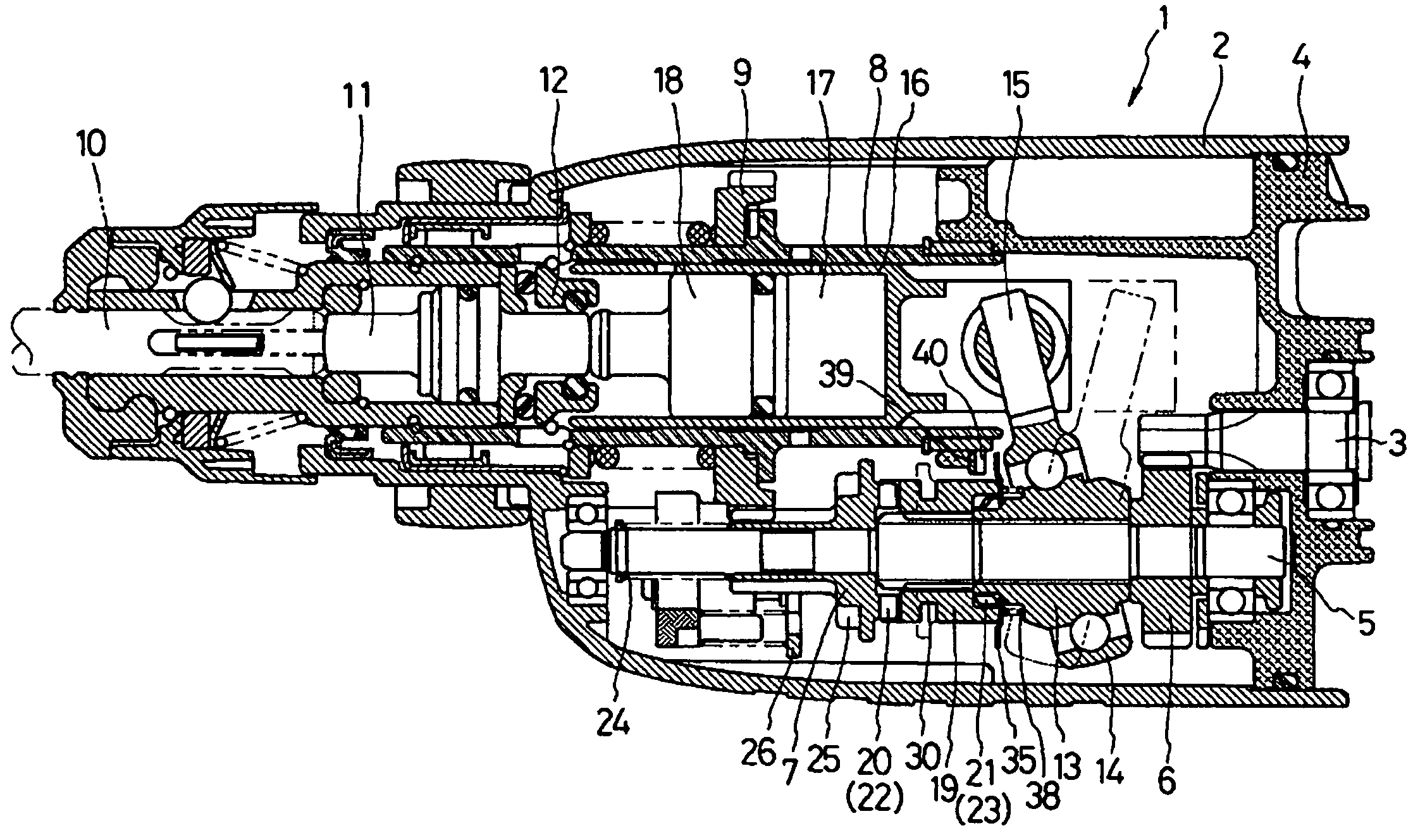
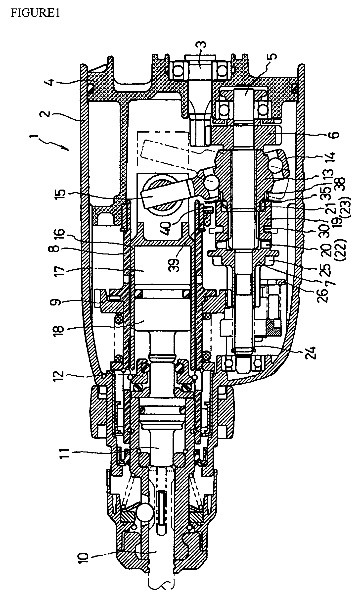
[0049]FIG. 1 is a partial cross-sectional side view of an essential part of a hammer drill 1 in accordance with the present invention. The hammer drill 1 includes a housing 2 which accommodates a motor (not shown) in the rear (to the right of FIG. 1) of the housing 2. The motor has an output shaft 3 rotatably supported by an inner housing 4 which is assembled to the interior of the housing 2. The output shaft 3 protrudes in the forward direction into the housing 2 and engages or meshes with a first gear 6 of an intermediate shaft 5 rotatably supported in parallel with the output shaft 3 within the housing 2. A separate second gear 7 is disposed on the forward portion of the intermediate shaft 5 in a manner that allows the second gear 7 to integrally rotate with the intermediate shaft 5 and axially slide with respect to or independently of the shaft 5. The second gear 7 engages a third gear 9 which rotates integrally with a tool holder 8 disposed in parallel with the intermediate sha...

embodiment 2

[0063]Another embodiment according to the present invention is described hereinafter with reference to the attached drawings, in which identical reference numerals are assigned to identical components, such as certain basic structures of the hammer drill, throughout the several views. Therefore, description of such elements is omitted.

[0064]FIG. 6 is an enlarged view of the clutch mechanism according to the second embodiment of the invention, showing a lock member, such as a lock sleeve 41, coupled to the boss sleeve 13. The lock sleeve 41 is comprised of a reduced diameter section 42 tightly fitted around the neck of the boss sleeve 13 immediately to the rear of the claws 23 and a large diameter section 43 which extends forward from the reduced diameter section 42 and into which the clutch 19 is loosely inserted. A plurality of axial grooves 44 is provided in the peripheral surface of the large diameter section 43 at regular intervals around the circumferential direction.

[0065]An e...

embodiment 3

[0071]Another embodiment according to the present invention is described hereinafter with reference to the attached drawings, in which as in the description of the second embodiment, identical reference numerals are assigned to identical components, such as certain basic structures of the hammer drill, throughout the several views. Therefore, description of such elements is omitted and only the clutch mechanism is described.

[0072]FIG. 9 is an enlarged view of the clutch mechanism according to the third embodiment of the present invention, showing a limiting member, such as a lock bar 48, extending from the switch plate 27. The lock bar 48 extends rearward alongside the inner housing 4 with its rear end portion 49 bent at a right angle toward the center axis of the piston cylinder 16. The bent portion 49 is configured such that its front surface L1 is located slightly forward of the rearmost position of the piston cylinder 16 (line L2 in FIG. 9) in the normal reciprocating stroke. In...


PUM

PropertyMeasurementUnit
Forceaaaaaaaaaa
Diameteraaaaaaaaaa
Lengthaaaaaaaaaa

Abstract

A hammer drill (1) includes a lock plate (35) forward of a boss sleeve (13) and a swash bearing (14) which cooperates with the boss sleeve to convert the rotation of an intermediate shaft (5) on which the boss sleeve is mounted. The lock plate is mounted on the boss sleeve and selectively engages claws (23) of the boss sleeve (13) in a manner that permits its integral rotation with and axial slide with respect to the boss sleeve. The lock plate is additionally biased in the forward direction by a coil spring (38) so that when a clutch (19) is shifted forward in a drill mode, the lock plate also moves forward into engagement with a stopper (39) secured to an inner housing (4), preventing inadvertent rotation of the boss sleeve.

Description

RELATED APPLICATION(S)[0001]This application claims priority on Japanese Patent Application No. 2002-337023 filed on Nov. 20, 2002.BACKGROUND OF THE INVENTION[0002]1. Field of the Invention[0003]The present invention generally relates to electric power tools. More particularly, the present invention relates to a hammer drill which allows selection of at least a drill mode and a hammer drill mode.[0004]2. Description of the Related Art[0005]A known hammer drill offers two selectable operating modes, a drill mode and a hammer drill mode. In the drill mode, the tool bit held by a chuck or other means at the top end of the housing is allowed to rotate without performing any percussive or hammer action. In the hammer drill mode, however, in addition to the rotary operation, a striker reciprocating rear of the tool bit delivers hammer blows either directly to the bit or indirectly to the bit via an impact bolt abutting the rear end of the bit. In this arrangement, as disclosed in Japan Pu...

Claims


Application Information

Patent Timeline
IPC IPC(8): E21B6/00B23B45/16B25D11/04B25D16/00B25D17/10
CPCB25D16/00B25D16/006B25D2216/0015B25D2216/0023B25D2216/0038B25D2216/0053B25D2250/191
Inventor SHIBATA, MITSUYOSHIFURUSAWA, MASANORIKAKIUCHI, YASUHIRO
Owner MAKITA CORP
Why Eureka
Try Eureka