Illuminating apparatus

Inactive Publication Date: 2005-12-13
CANON KK
View PDF11 Cites 136 Cited by
  • Summary
  • Abstract
  • Description
  • Claims
  • Application Information

AI Technical Summary

Benefits of technology

[0017]From the foregoing, the greatest task to be achieved by the present invention is to propose a thin type illuminating optical system comprised of necessary minimum parts an

Problems solved by technology

In this proposition for preventing lateral stripe-shaped uneven light distribution, however, the one more optical member is required and this has led not only to an increase in cost, but also to the necessity of an extra space in the longitudinal direction of the optical system.
Also, in terms of an optical characteristic, even a component which originally nee

Method used


Image

  • Illuminating apparatus
  • Illuminating apparatus
  • Illuminating apparatus

Examples


first embodiment

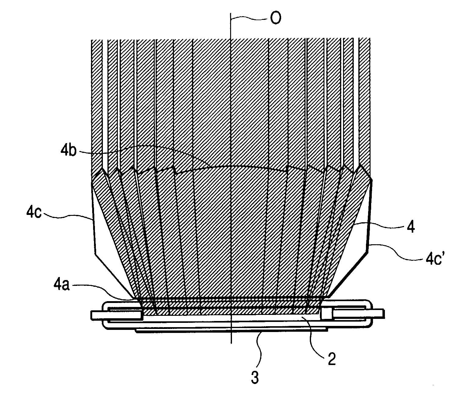
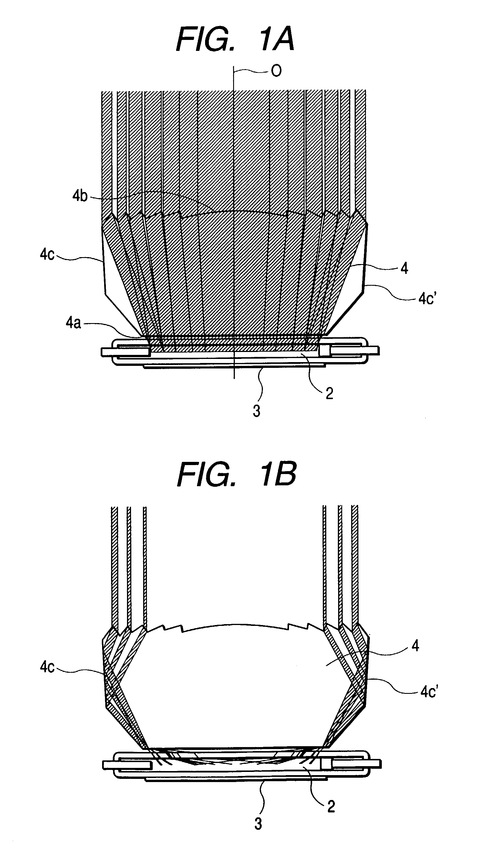
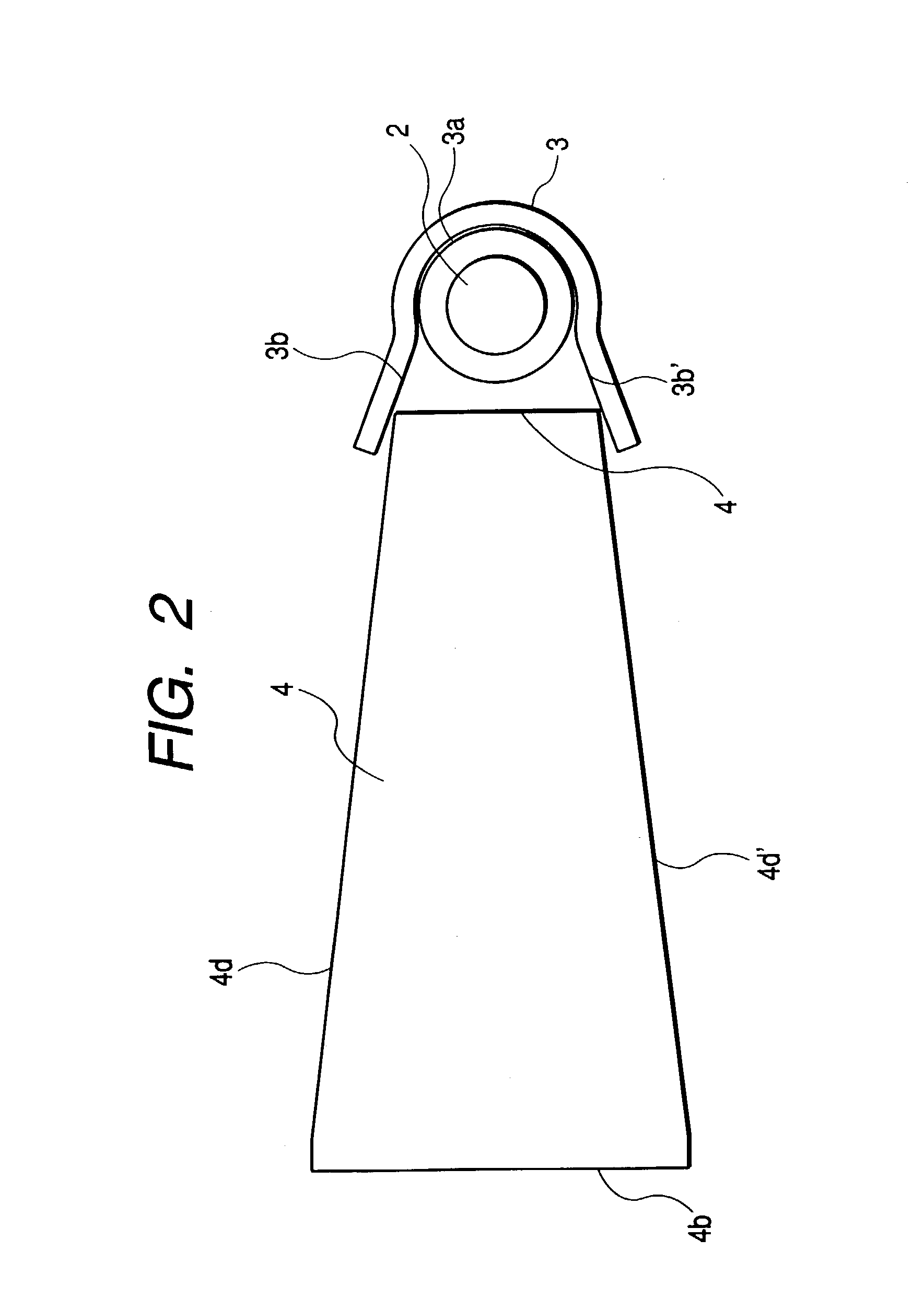
[0056]FIGS. 1A, 1B and FIGS. 2 to 4 show an illuminating apparatus according to the present invention, and particularly in the present embodiment, a flashlight emitting apparatus, FIGS. 1A and 1B being cross-sectional views of essential portions constituting the optical system of the flashlight emitting apparatus taken along a plane containing the center axis of the flashlight discharge tube thereof, FIG. 2 being a longitudinal cross-sectional view of the essential portions constituting the optical system of the flashlight emitting apparatus, FIG. 3 being an exploded perspective view of only the main optical system of the flashlight emitting apparatus, and FIG. 4 being a perspective view of a camera to which the present invention is applied. In FIGS. 1A and 1B, there is also shown the trace of a representative ray of light emitted from a light source.

[0057]FIGS. 1A and 1B show the optical path of only a beam travelling toward the center of an optical axis on an irradiated surface am...

second embodiment

[0129]the present invention will now be described with reference to FIG. 7.

[0130]FIG. 7 shows an illuminating apparatus according to the second embodiment of the present invention, and particularly in this embodiment, a flashlight emitting apparatus, and shows a perspective view of only the main optical system thereof.

[0131]In FIG. 7, the reference numeral 22 designates a flashlight discharge tube (xenon tube), and the reference numeral 23 denotes a reflector having a construction substantially similar to that of the first embodiment. The reference numeral 24 designates an illuminating beam directing optical member for causing a beam directly emitted from the flashlight discharge tube 22 and the beam reflected by the reflector 23 and incident thereon to be efficiently applied to the object side. As in the first embodiment, an optical resin material of high transmittance such as acrylic resin or a glass material is suitable as the material of the optical member 24.

[0132]This second e...


PUM


Abstract

This specification discloses an illuminating apparatus having a light source and an optical unit disposed forwardly on the object side of the light source, the optical unit being provided with an incidence surface on which light from the light source is incident, a light emergence surface provided with a Fresnel lens, and a side reflecting surface for totally reflecting the light incident on the incidence surface toward the Fresnel lens, wherein the light totally reflected by the side reflecting surface is refracted by the Fresnel lens and efficiently irradiates the object.

Description

BACKGROUND OF THE INVENTION[0001]1. Field of the Invention[0002]This invention relates to an illuminating apparatus, and particularly to an illuminating apparatus suitable for an optical apparatus having no surplus in the vertical thickness thereof and a photographing apparatus using the same, and is suitable for being mounted, for example, on a portion of the main body of a camera (the main body of a photographing apparatus), and operatively associated with the photographing operation of the main body of the camera to efficiently apply illuminating light (flashlight) to an object side and photograph the object.[0003]2. Description of the Prior Art[0004]Heretofore, an illuminating apparatus used in a photographing apparatus such as a camera has been comprised of a light source and optical parts such as a reflector and a Fresnel lens for forwardly directing a beam emitted from the light source.[0005]In such an illuminating apparatus, various propositions have heretofore been made in ...

Claims


Application Information

Patent Timeline
IPC IPC(8): F21V5/04F21V7/00
CPCF21V5/045F21V7/0091G03B15/03
Inventor TENMYO, YOSHIHARU
Owner CANON KK
Why Eureka
Try Eureka