Irradiation apparatus and irradiation method

Inactive Publication Date: 2006-01-10
MITSUBISHI ELECTRIC CORP
View PDF3 Cites 251 Cited by
  • Summary
  • Abstract
  • Description
  • Claims
  • Application Information

AI Technical Summary

Benefits of technology

[0010]The object of the present invention is to provide an irradiation apparatus and method capable of providing a large irradiation field while ensuring the flatness of a radiation dose distribution in the irradiation field without strengthening the performance of the particle accelerator or the irradiation field enlarging device.

Problems solved by technology

However, there may also be some cases requiring irradiation fields larger than the above-mentioned one.
Thus, it is difficult to further enlarge such a structure even in terms of cost as well as accuracy.
In the Wobbler electromagnet, however, there arises a problem that when the magnetic field strength is increased to generate an alternating magnetic field, ac loss due to the eddy current generated in the iron core of the magnet becomes large, thereby heating the iron core to a high temperature.
Moreover, although a strategy of lengthening the magnetic poles of the electromagnet can be conceived, too, it is undesirable from the viewpoint of keeping the rotating gantry small.
In this case, however, beams passing through the scatterer are decelerated therein, so increasing the thickness of the scatterer shortens the range of the beams inside the target.
Therefore, there is also a limit to the thickness of the double scatterer to be used.

Method used


Image

  • Irradiation apparatus and irradiation method
  • Irradiation apparatus and irradiation method
  • Irradiation apparatus and irradiation method

Examples


embodiment 1

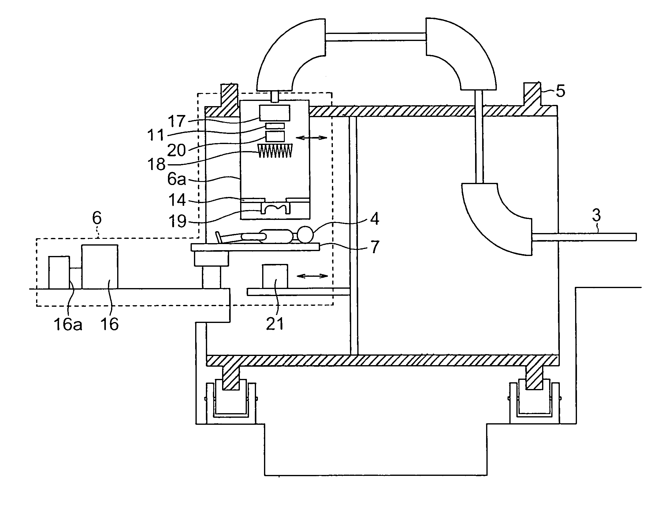
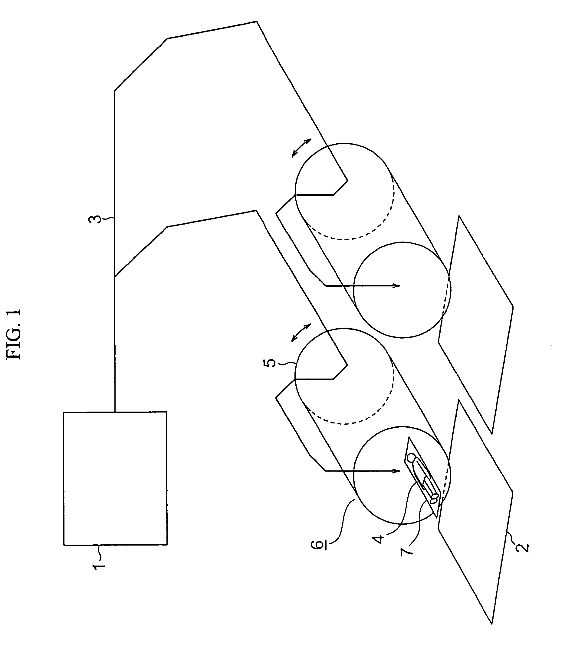
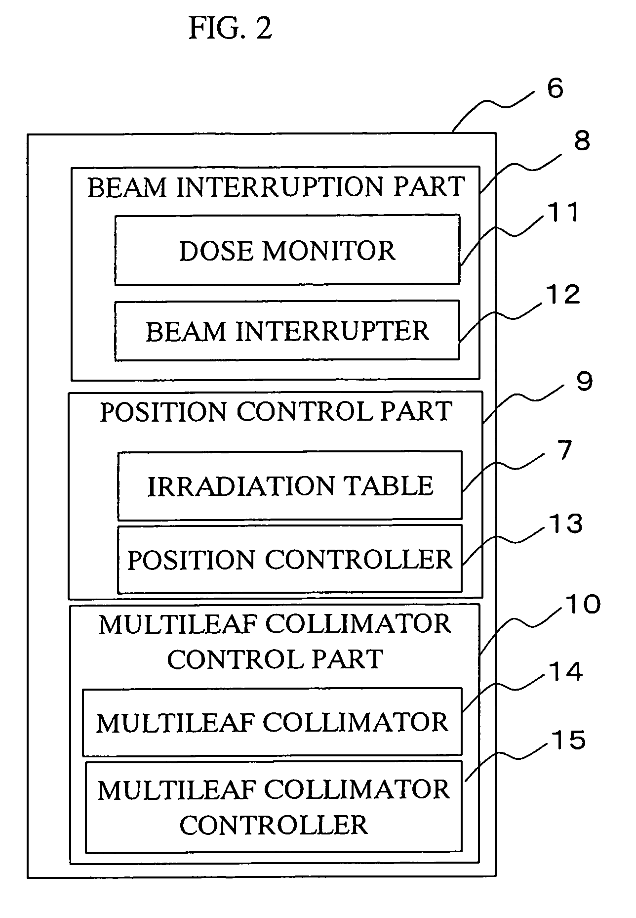
[0051]FIG. 1 shows the schematic construction of an irradiation system including irradiation apparatuses constructed in accordance with the principles of the present invention. FIG. 2 is a block diagram that shows an irradiation apparatus in the irradiation system of FIG. 1. FIG. 3 is a constructional view that shows a rotating gantry and an irradiation apparatus in the irradiation system of FIG. 1. FIG. 4 is a block diagram of a control unit in the irradiation apparatus of FIG. 3. FIG. 5 is a conceptual diagram that shows the structure of a multileaf collimator in the irradiation apparatus of FIG. 3. FIG. 6 is a conceptual diagram that shows the structure of a ridge filter in the irradiation apparatus of FIG. 3. FIG. 7 is a conceptual diagram that shows the structure of a compensating filter in the irradiation apparatus of FIG. 3. In the following, the irradiation apparatus will be described as being applied to a radiotherapy apparatus by way of example, but the present invention i...

embodiment 2

[0098]FIGS. 23A through 23D are plan views explaining the movement of the leaves of a multileaf collimator in an irradiation apparatus according to a second embodiment of the present invention, wherein FIG. 23A shows the initial positions of the leaves in which they are all closed; FIG. 23B shows that a first pair of leaves are opened with the remaining leaves being closed; FIG. 23C shows that a second pair of leaves are subsequently opened with the remaining leaves other than the first and second pairs being closed; and FIG. 23D shows that the last pair of leaves are finally opened.

[0099]In the first embodiment, the direction in which the leaves are driven to move is parallel to the slope of the dose distribution, but this second embodiment is constructed such that the moving direction of the leaves is perpendicular to the slope of the dose distribution. In this case, each time a predetermined amount of dose is irradiated with partial irradiation, i.e., each time the irradiation of...

embodiment 3

[0101]FIGS. 24A and 24B show individual and total dose distributions, respectively, when an irradiation apparatus according to a third embodiment of the present invention is used.

[0102]In the above-mentioned first embodiment, the dose in the overlapping zone has been decreased at a constant slope from the non-overlapping zone toward its adjoining irradiation zones, but according to this third embodiment, in order to reduce the flatness in the dose distribution in an important area 32 in which the dose distribution flatness is particularly critical, the slope of the dose distribution in the important area 32 is made gradual, with the dose distribution slope in the other portions of the overlapping zone being made steep in comparison with that in the important area 32, as shown in FIGS. 23A through 23D.

[0103]This irradiation apparatus is able to make the overlapping error of the dose in the overlapping zone smaller for concentrated administration thereof.

[0104]Although in the foregoin...


PUM


Abstract

An irradiation apparatus has a large irradiation field and is capable of ensuring the uniformity of a dose distribution without strengthening the performance of an irradiation field enlarging device. The irradiation apparatus includes a beam interruption part for performing a plurality of irradiations of a radiation beam, a position control part for controlling a location to be irradiated in such a manner that the entire surface of the target can be irradiated in a plurality of irradiation zones including an overlapping area formed by the plurality of irradiations, and a multileaf collimator control part for providing a slope to a dose distribution in the overlapping area of the respective irradiation zones, so that the dose distribution over the entire surface of the target including the overlapping area is made flat or uniform by the plurality of irradiations of the radiation beam.

Description

BACKGROUND OF THE INVENTION[0001]1. Field of the Invention[0002]The present invention relates to an irradiation apparatus for irradiating particle beams or corpuscular rays to a location to be irradiated as well as an irradiation method using this apparatus.[0003]2. Description of the Related Art[0004]Known methods of enlarging the irradiation field of an irradiation apparatus, which treats cancer by using such a kind of particle beams, generally include a double scatterer method and a Wobbler method. In the double scatterer method, there are arranged two scatterers through which a particle beam passes so that a uniform dose distribution can be formed. On the other hand, in the Wobbler method, a particle beam is irradiated on a scatterer while being moved in a circle by means of an electromagnet so that a uniform dose distribution can be formed in the vicinity of the center of the circle. The field of irradiation thus obtained is usually of an area of from about 15 cm×15 cm to about...

Claims


Application Information

Patent Timeline
IPC IPC(8): H01J37/09A61N5/00G21K1/04A61N5/10G21K3/00G21K5/04G21K5/10
CPCG21K1/046G21K1/04A61N5/1045
Inventor HARADA, HISASHI
Owner MITSUBISHI ELECTRIC CORP
Why Eureka
Try Eureka