Electrical contact

a technology of electrical contacts and contacts, applied in the direction of coupling contacts, coupling devices, coupling devices, etc., can solve the problems of signal instability, inability to meet the requirement of providing adequate normal force to electrical contacts, and increasing the size of conventional electrical connectors

Inactive Publication Date: 2006-01-24
HON HAI PRECISION IND CO LTD
View PDF12 Cites 8 Cited by
  • Summary
  • Abstract
  • Description
  • Claims
  • Application Information

AI Technical Summary

Benefits of technology

[0008]Accordingly, an object of the present invention is to provide a type of electrical contacts, whose structure can enable an electrical connector with this type of electrical contacts assembled to transmitting signals more stably.

Problems solved by technology

Inadequate normal force between the electrical contacts and electrical elements of the complementary connector easily causes signal instability.
However, with the development toward miniaturization and integration of the electronic devices, the electrical connector not only become more and more smaller than before but also required to transmitting signal more stably.
Thus, the configuration of the conventional electrical connector cannot fulfill the requirement of providing adequate normal force on the electrical contacts.

Method used


Image

  • Electrical contact
  • Electrical contact
  • Electrical contact

Examples


Embodiment Construction

[0015]Reference will now be made in detail to the preferred embodiment of the present invention.

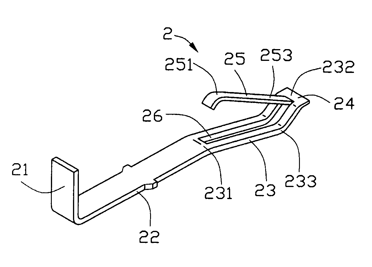
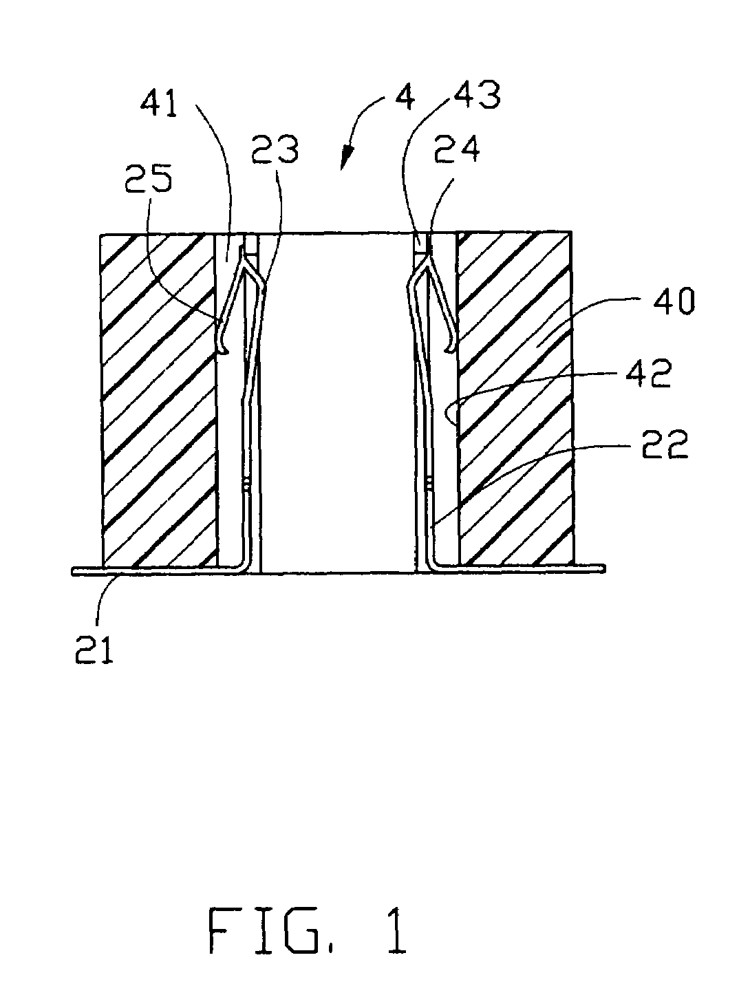
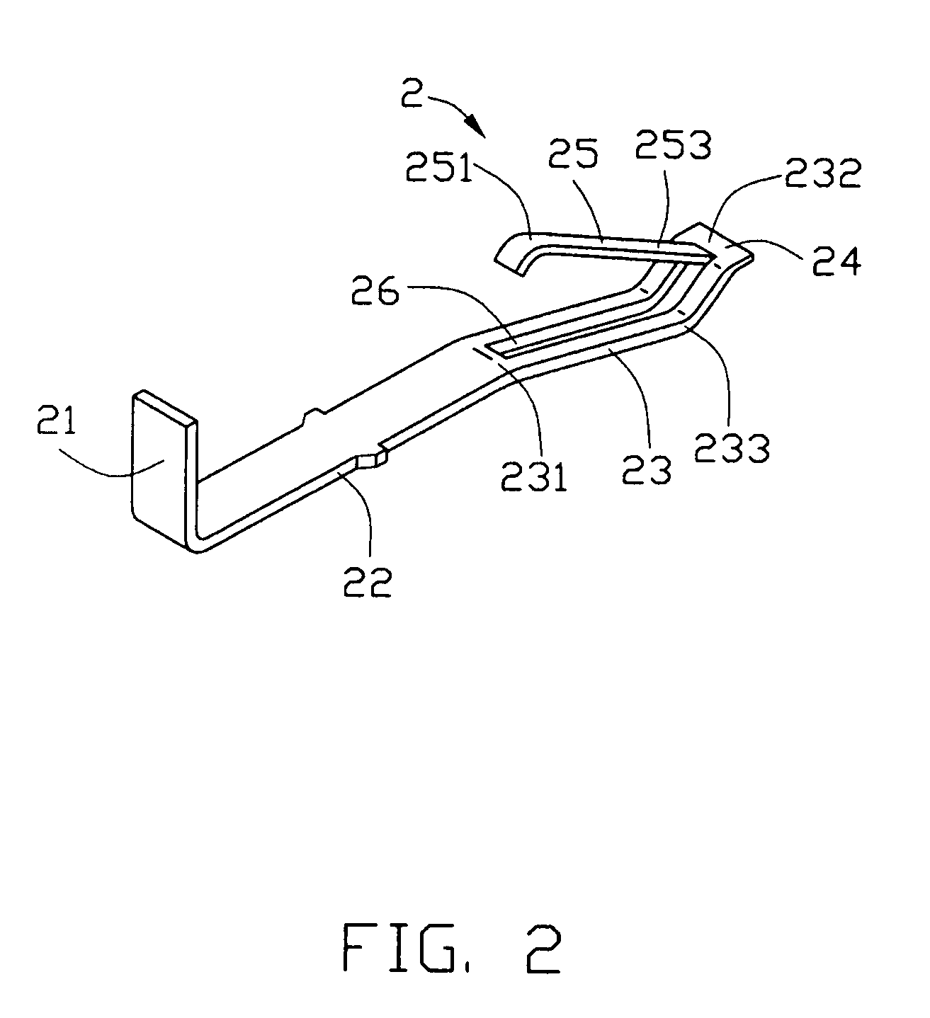
[0016]Referring to FIG. 1 and FIG. 2, an electrical connector 4 comprises an insulated housing 40 and a plurality of electrical contacts 2. The housing 40 includes a plurality of passageways 41 for respectively receiving the electrical contacts 2 and a plurality of protrusions 43 respectively projecting from an inner wall 42 of corresponding passageway 41. Each electrical contact 2 comprises a mating portion 23 for electrically contacting with an electrical element of a complementary connector (not shown), a preload portion 24 extending forwardly from one end 232 of the mating portion 23, a retention portion 22 extending rearwardly from the mating portion 23 to engage with the housing 40 and a solder portion 21 extending from the retention portion 22 to solder the electrical connector 4 to a printed circuit board (not shown). The mating portion 23 comprises a tab 25 projecting from the en...


PUM


Abstract

An electrical contact (2) comprises a mating portion (23), a preload portion (24) extending away from the mating portion, a retention portion (22) extending from the mating portion and a solder portion (21) for soldering the electrical contact to a printed circuit board. The mating portion has a tab resiliently abutting against the housing. The preload portions and the tabs of the electrical contacts ensure a reliable electrical connection between the electrical contacts and electrical elements mating with the electrical contacts.

Description

BACKGROUND OF THE INVENTION[0001]1. Field of the Invention[0002]The present invention is generally related to a type of electrical contacts, and more particularly, to a type of electrical contacts used in card connectors, battery connectors or board to board connectors.[0003]2. Description of Related Art[0004]A variety of electrical connectors are widely used in electronic devices for transmitting signals between them. Electrical connectors each comprise a plurality of electrical contacts for contacting with electrical elements of a complementary connector. For achieving reliable and continuous signals between the electronic devices, the electrical contact must be applied with adequate normal force when the electrical connector with the electrical contacts assembled mates with the complementary connector. Inadequate normal force between the electrical contacts and electrical elements of the complementary connector easily causes signal instability.[0005]U.S. Pat. No. 5,971,809 (the '...

Claims


Application Information

Patent Timeline
Patent Type & Authority Patents(United States)
IPC IPC(8): H01R4/48H01R13/24
CPCH01R12/721H01R13/245
Inventor ZHANG, CHI
Owner HON HAI PRECISION IND CO LTD
Why Eureka
Try Eureka