Wheel structure

a technology of wheels and wheels, applied in the field of wheels, can solve the problems of increasing the cost of manufacture and assembly, difficulty in controlling the turning movement, and carts (a) still may encounter the possibility of overturning, so as to save assembly time, reduce manufacturing costs, and stable riders

Inactive Publication Date: 2006-09-14
FAR GREAT PLASTICS INDAL
View PDF8 Cites 7 Cited by
  • Summary
  • Abstract
  • Description
  • Claims
  • Application Information

AI Technical Summary

Benefits of technology

[0007] It is the primary objective of the present invention to provide a wheel structure, which provides with more contact surfaces for a cart to get in touch with the ground and more stable to riders.
[0008] It is another objective of the present invention to provide a wheel structure, which uses less parts to save time in assembly and has less noise.
[0009] It is a further objective of the present invention to provide a wheel structure, which comprises a main wheel body and auxiliary sections formed integrally by blowing molding or injection molding. The wheel is provided with an outer tire formed in an injection or casting method or mounted to the wheel, thus it is cost effectiveness

Problems solved by technology

When the cart (A) makes a turn, it is difficult to control turning movement because the wheels (B) are small in size.
However, if the turning angle is too big, the cart (A) still may encounter the possibility of overturning.
However, the auxiliary wheels (D1) increase the cost of manufacture and assembly, and it easily malfunctions.

Method used


Image

  • Wheel structure
  • Wheel structure
  • Wheel structure

Examples


first embodiment

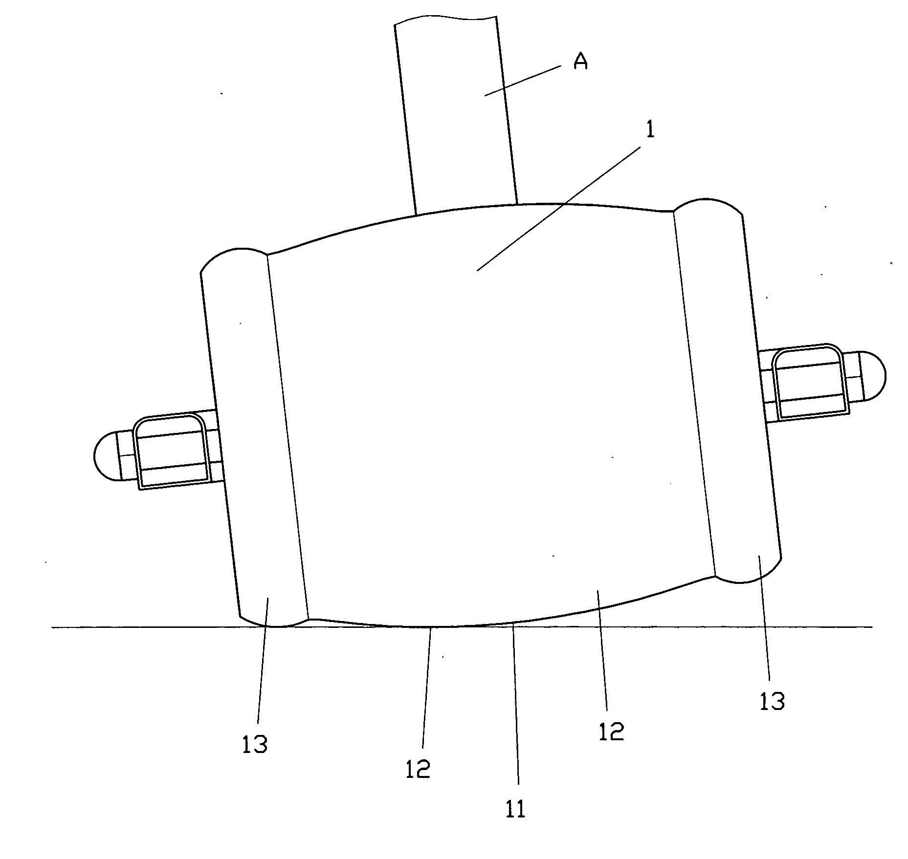
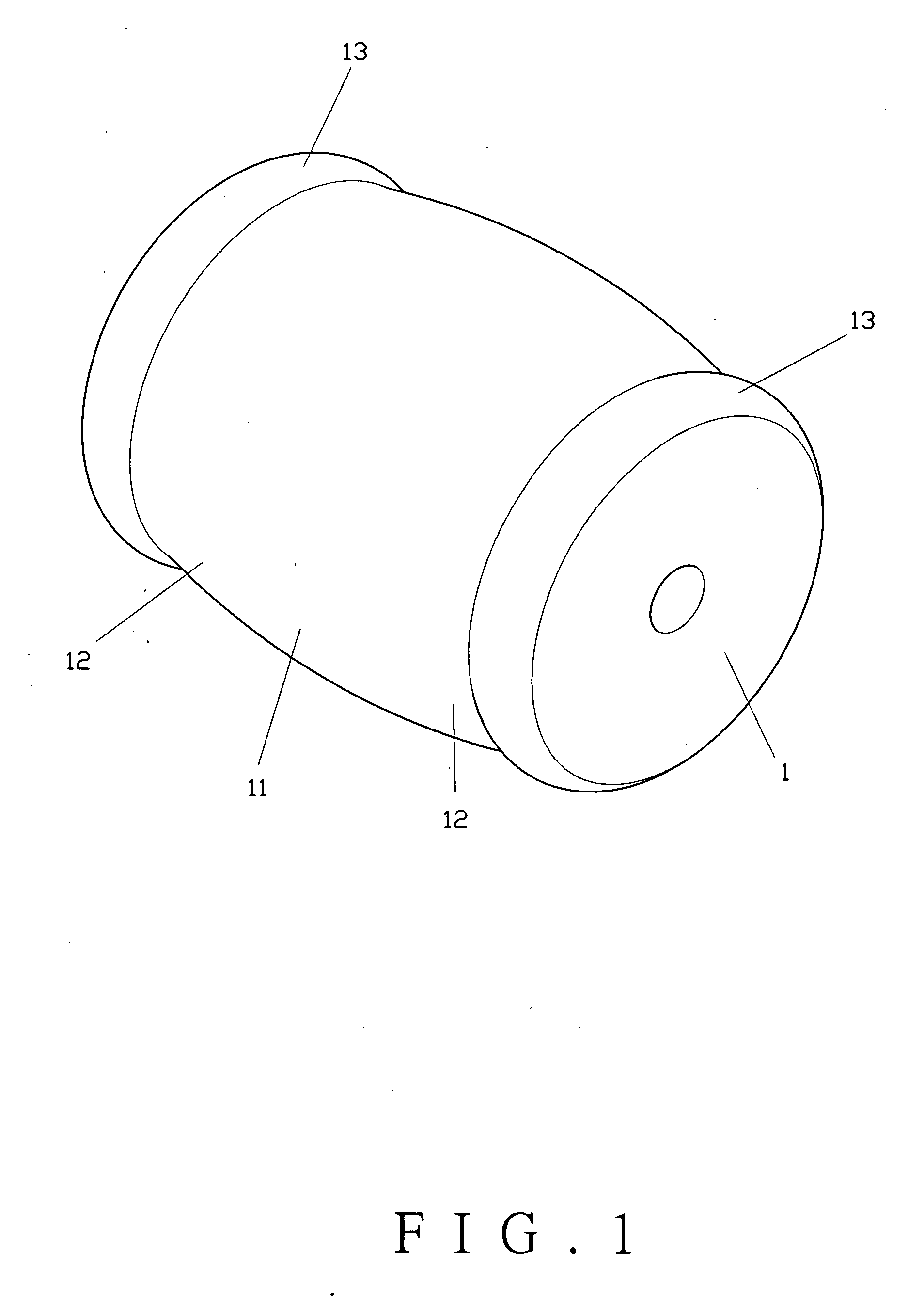
[0021] As shown in FIG. 1, the present invention comprises a wheel (1) having a main wheel body (11) at the center portion for direct contact with the ground. The main wheel body (11) has its two sides extending to form a pair of extension sections (12) to get in touch with the ground when making turns. Each extension section (12) extends outwardly to form an auxiliary section (13). The main wheel body (11) of the wheel (1) has a larger outer diameter than the outer diameters of the auxiliary sections (13) to increase the contact surfaces with the ground when making turns. The auxiliary sections (13) are integral to the main wheel body (11).

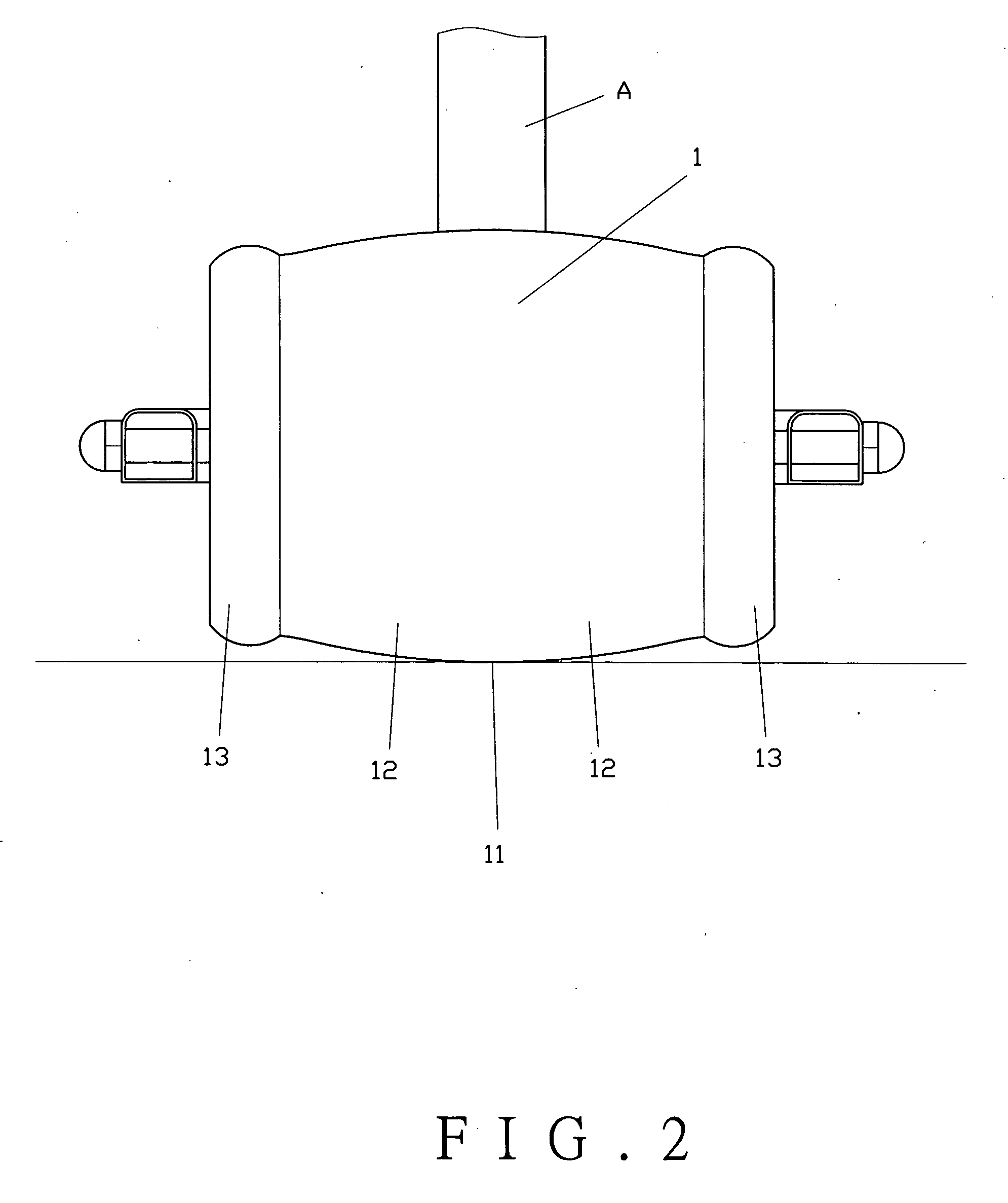
[0022] To operate the present invention, as shown in FIGS. 2 and 3, the wheel (1) is pivotally connected to a cart (A). When the cart (A) is rolling in a straight direction, the main wheel body (11) of the wheel (1) remains contact with the ground. When the cart (A) makes a turn, due to the centrifugal force, the wheel (1) will incline with the c...

second embodiment

[0023] the present invention comprises a wheel (1A) as shown in FIG. 4. The wheel (1A) has a main wheel body (11A) at the center portion, a pair of extension sections (12A) extending from respective sides of the main wheel body (11A), and a pair of auxiliary sections (13A) coaxially extending from the extension sections (12A), respectively. The main wheel body (11A) of the wheel (1A) has a larger outer diameter than the outer diameters of the auxiliary sections (13A). The extension sections (12A) are spaced from the auxiliary sections (13A).

third embodiment

[0024] the present invention comprises a wheel (1B), as shown in FIG. 5. The wheel (1B) comprises a main wheel body (11B) at the center portion to be in touch with the ground when the cart is rolling. The main wheel body (11B) has its two sides extending outwardly to form a pair of extension sections (12B) and a pair of auxiliary sections (13B) coaxially extending from the extension sections (12B), respectively. The main wheel body (11B) of the wheel (1B) has a larger outer diameter than the outer diameters of the auxiliary sections (13B). The extension sections (12B) are spaced from the auxiliary sections (13B).


PUM


Abstract

A wheel structure includes a main wheel body, a pair of extension sections extending from respective sides of the main wheel body, and a pair of auxiliary sections coaxially extending from the extension sections, respectively. The main wheel body of the wheel has a larger outer diameter than the outer diameters of the auxiliary sections. Both the main wheel body and the auxiliary sections are provided with outer tires made in a different material. The wheel increases contact surfaces with the ground when making turns, so as to prevent overturning.

Description

BACKGROUND OF THE INVENTION [0001] 1. Field of the Invention [0002] This invention relates to a wheel structure applied to playing or sporting vehicles such as scooters, tricycles, bicycles, skateboards, roller skates, training cycles, hand-pulling suitcases, hand carts, shopping carts, toy carts or balancing wheels, and more particularly to a wheel having two auxiliary sections at respective sides of a main wheel body to increase contact surfaces of the wheel with the ground. [0003] 2. Description of the Prior Art [0004] Most scooters, tricycles or bicycles for children are mounted with wheels (B) to a cart (A), as shown in FIG. 8, to facilitate movement of the cart (A). When the cart (A) makes a turn, it is difficult to control turning movement because the wheels (B) are small in size. Sometimes the cart (A) may even turnover if the turn is made too wide. [0005] In order to correct the shortcoming, an egg-shaped wheel (C) was derived, as shown in FIG. 9, to provide the stability w...

Claims


Application Information

Patent Timeline
Patent Type & Authority Applications(United States)
IPC IPC(8): B60B1/00
CPCA63C17/24B60B3/001B60B5/02B60B19/12B60B33/0028B60B2200/43B60B2200/45B60B2200/47B60B2310/204B60B2900/113B60B2900/133B60Y2200/13B60Y2200/81
Inventor CHEN, TING-HSING
Owner FAR GREAT PLASTICS INDAL
Why Eureka
Try Eureka