
Clip applier

a clip and applicator technology, applied in the field of clip applicators, can solve problems such as heavy burden on patients, and achieve the effect of facilitating smooth operation

Inactive Publication Date: 2011-11-29
MACHIDA ENDOSCOPE
View PDF10 Cites 133 Cited by
  • Summary
  • Abstract
  • Description
  • Claims
  • Application Information

AI Technical Summary

Benefits of technology

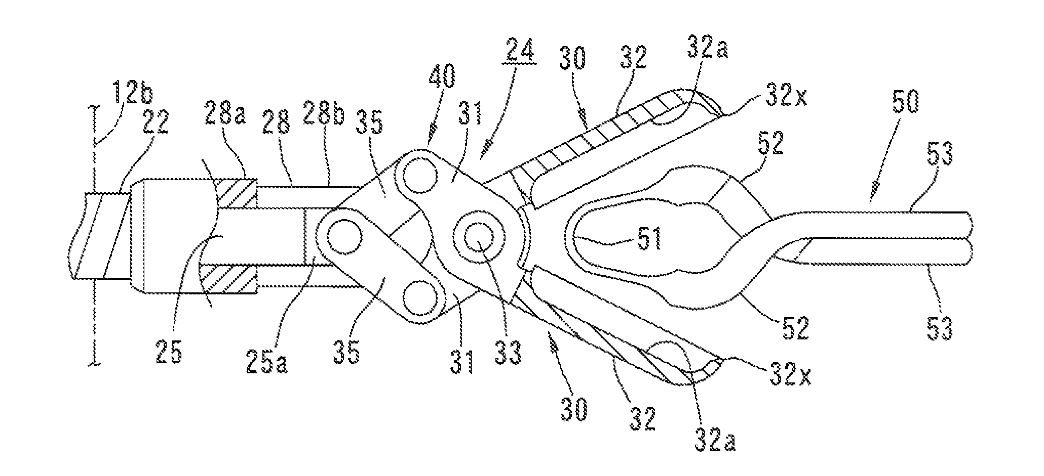
[0007]In the above mentioned arrangement, when the clip applier is inserted through the endoscope, the clip can be applied to the affected area while being observed with the endoscope. This allows a ligation to be performed without widely opening the body of a patient. The clip applier also allows the pair of clip portions of the clip to be smoothly opened by a wire drawing operation. When the operating force is released with the affected area placed between the opened clip portions, the pair of clip portions are closed by the elastic force of the hinge portion of the clip, surely ligating the affected portion.
[0009]In this arrangement, when the clip applier is inserted through a flexible endoscope, the applier body can be held in a stable posture with respect to the endoscope by clamping and fixing the hard portion with a clamping means provided in the endoscope. This eliminates the necessity of manpower for holding the applier body.
[0015]In this arrangement, a pulling force of the wire can be smoothly and securely transmitted to the clamp members by the link mechanism.
[0019]This allows the clip to be observed without being obstructed by the gripping portions of the clamp members in a field of view of the endoscope, further facilitating smooth conduct of the operation.

Problems solved by technology

However, in the above mentioned operation, it is required to widely open the cranium, which tends to cause a heavy burden on a patient.

Method used


Image

  • Clip applier
  • Clip applier
  • Clip applier

Examples


Embodiment Construction

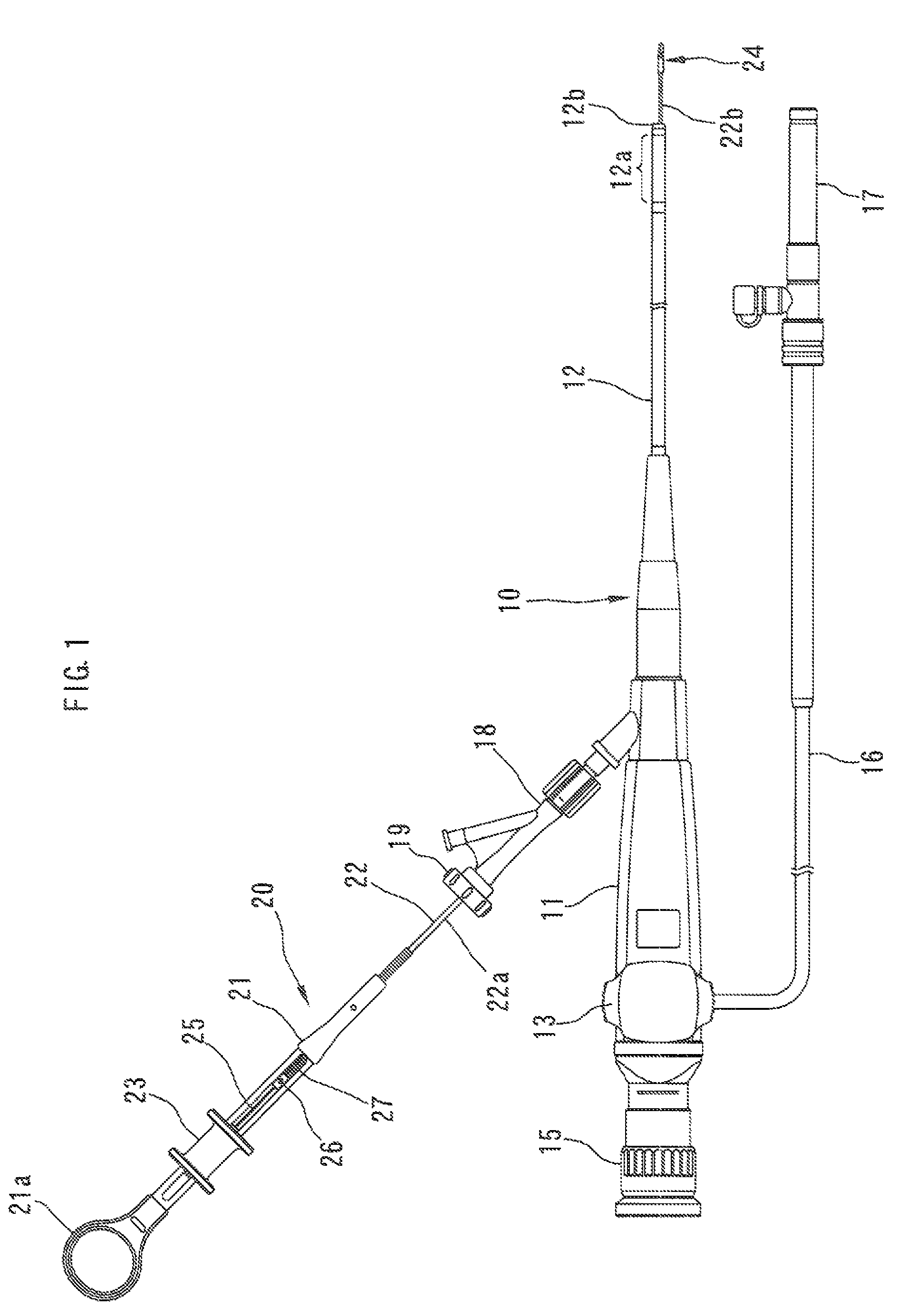
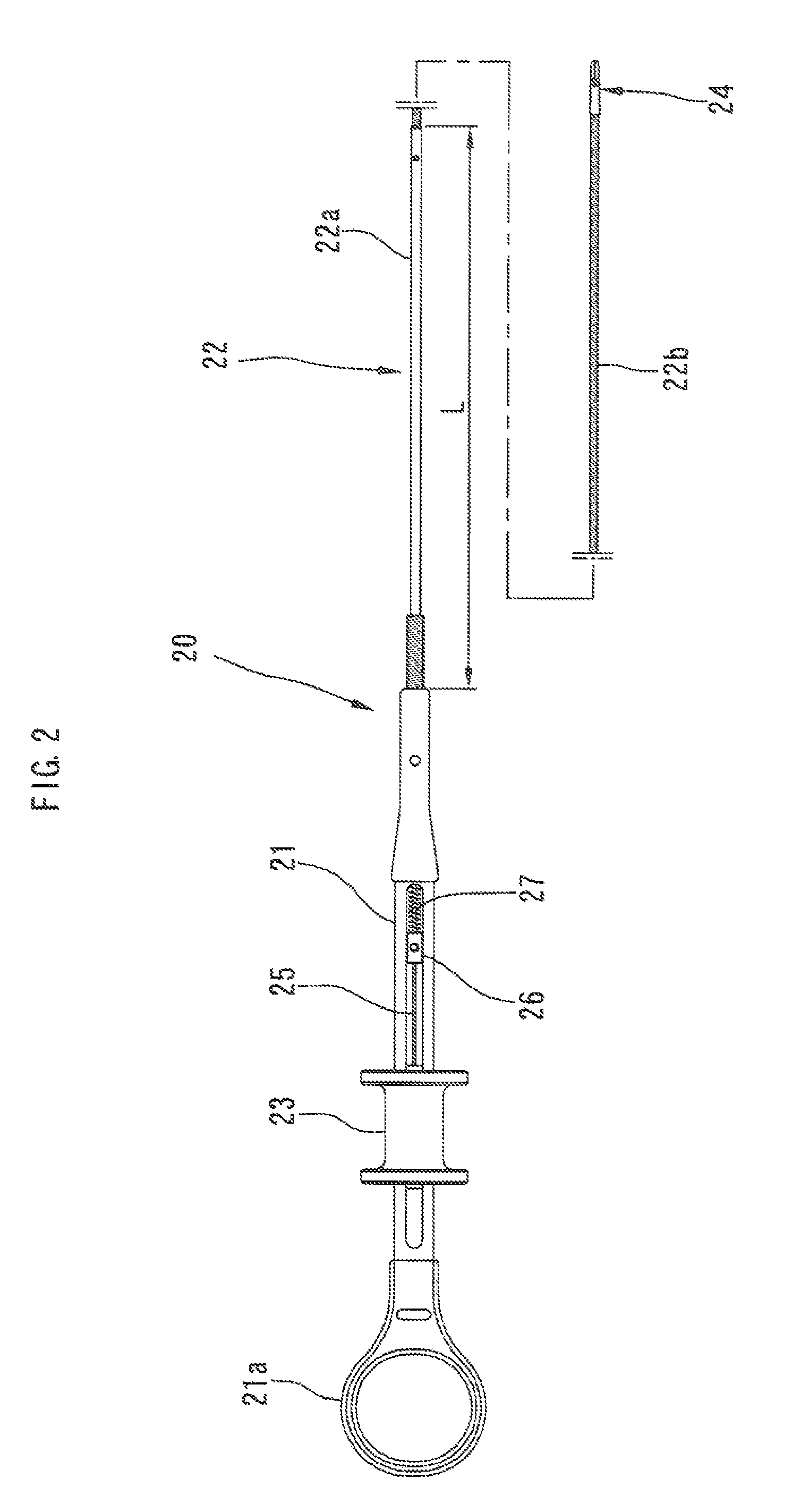
[0051]A clip applier for use with an endoscope according to a first embodiment of the present invention will now be described with reference to FIGS. 1 to 4.

[0052]FIG. 1 shows an endoscope for brain surgery 10 and a clip applier 20 to be used with the endoscope 10.

[0053]The endoscope 10 will be described first. The endoscope 10 includes an elongated endoscope body 11 and a long flexible insertion portion 12 extending from a distal end of the body 11. The insertion portion 12 includes a bendable portion 12a extending a predetermined length form a distal end of the insertion portion 12. The bendable portion 12a can be bent by operating an operation portion 13 disposed on the body 11.

[0054]The insertion portion 12 further includes a hard tip 12b fixed at a distal end of the bendable portion 12a. An objective optical system (not shown) is received in the tip 12b adjacent to an observation window formed in an end surface of the tip 12b.

[0055]An ocular portion 15 having a built-in ocular...


PUM


Abstract

A clip applier includes a body 21, an insertion tube 22 extending from the body 21 and inserted in a channel of an endoscope and a clamp mechanism 24 disposed at a distal end of the insertion tube 22. The clamp mechanism 24 has a support member 28 fixed at the distal end of the insertion tube 22 and a pair of clamp members 30 rotatably supported by the support member 28. The clamp members 30 are connected to a distal end of a wire 25 via a pair of links 35. The clamp members 30 respectively include gripping portions 32 protruding form the support member 28. A clip 50 is received in receiving grooves 32a of the gripping portions 32. When the wire 25 is pulled by operating an operation member disposed on the body 21, the clamp members 30 are rotated against an elastic force of a hinge portion 51 of the clip 50, thereby causing a pair of clip portions 53 of the clip 50 to be opened.

Description

BACKGROUND OF THE INVENTION[0001]This invention relates to a clip applier for use in brain surgery, etc.[0002]To prevent rupture of an aneurysm in the brain, for example, an operative treatment is performed in which a neck of the aneurysm is ligated with a clip to block the communication between the aneurysm and the blood vessel.[0003]A clip used in the operation integrally includes a hinge portion, a pair of clip portions and a pair of connecting portions respectively connecting opposite ends of the hinge portion to the pair of clip portions. The connecting portions intersect with each other. The pair of clip portions are biased to be closed by an elastic force of the hinge portion.[0004]In the operation, a cranium is widely opened and the clip is applied to an affected area, e.g. the neck of the aneurysm, using a tweezers-like instrument while the affected area is being observed with a microscope. As shown in Japanese Utility Model Publication No. H7-41447, the instrument includes...

Claims


Application Information

Patent Timeline
Patent Type & Authority Patents(United States)
IPC IPC(8): A61B17/04
CPCA61B17/1285A61B17/1227
Inventor MIYAGI, KUNIHIKOMISAWA, MASAYUKI
Owner MACHIDA ENDOSCOPE
Learn More