Cap

a technology of cap cover and cap cover, which is applied in the field of caps, can solve the problems of deteriorating a movement of the manipulation body, inability of users to easily open the cap cover with one hand, and inability of the manipulation body to slide smoothly, etc., and achieves the effects of convenient manufacturing, convenient assembly operation, and smooth opening

Active Publication Date: 2009-11-03
M F V
View PDF13 Cites 27 Cited by
  • Summary
  • Abstract
  • Description
  • Claims
  • Application Information

AI Technical Summary

Benefits of technology

[0010]The present invention has been made in view of the conventional problems. It is an object of the present invention to provide a cap which can be smaller in number of constituent elements, easy to manufacture with simple assembly operation, and of which cap cover can be smoothly opened with one hand for a long period of time.
[0021]According to the present invention, the manipulation body includes the elastic connection rod arranged on the side of the outlet below the support, the manipulation portion is provided on one end of the elastic connection rod, the pressing portion is provided on the other end of the elastic connection rod, and the manipulation portion is connected to the support via the deformable connection piece so as to allow the movement of the manipulation body relative to the support. Due to this, the support and the manipulation body can be formed integrally with each other and the number of constituent elements of the cap can be reduced, thereby facilitating a cap assembly operation.
[0022]Moreover, when the manipulation portion is pressed, then the pressing portion of the manipulation body first abuts on the opening / closing hinge of the container main body and then the elastic connection rod elastically deforms to follow the movement of the manipulation portion of the manipulation body. Due to this, when the cap cover starts opening, it is possible to effectively relax and absorb a force with which the pressing portion presses the opening / closing hinge, prevent the pressing portion to strongly press the opening / closing hinge with an excessively strong force at one time, effectively prevent the opening / closing hinge from being broken or damaged and smoothly and surely open the cover cap for a long period of time. Moreover, the manipulation body is arranged in a top portion of the cap main body to be longitudinally movable and the support is fixedly attached to the cap main body so as to close an area between the outlet and the manipulation body above the manipulation body. Due to this, the support can protect the content ejected from the outlet from flowing out toward the manipulation body. It is thereby possible to prevent the content of the container from adhering to the manipulation body and open the cap cover smoothly for a long period of time.

Problems solved by technology

Due to this, a resistance between the manipulation body and the cap main body increases, which often makes it impossible for the manipulation body to smoothly slide.
This gradually deteriorates a movement of the manipulation body, with the result that the user is often incapable of easily opening the cap cover with one hand.
This makes manufacturing of the cap complicated and cumbersome.
Furthermore, it is necessary to separately assemble the support and the manipulation body with the cap main body, resulting in a complicated cap assembly operation.
Moreover, both the former and latter conventional caps have the following common problems.
Due to this, in the case where an opening / closing operation for opening / closing the cap cover is repeated, then the opening / closing hinge is broken or damaged, with the result that the cap cover cannot be smoothly opened or closed after use of a short period of time.
Due to this, in the case where the content adheres to the manipulation body, the sliding operation of the manipulation body is adversely influenced.

Method used


Image

  • Cap
  • Cap
  • Cap

Examples


Embodiment Construction

[0037]Embodiments of the present invention will be described hereinafter based on the drawings.

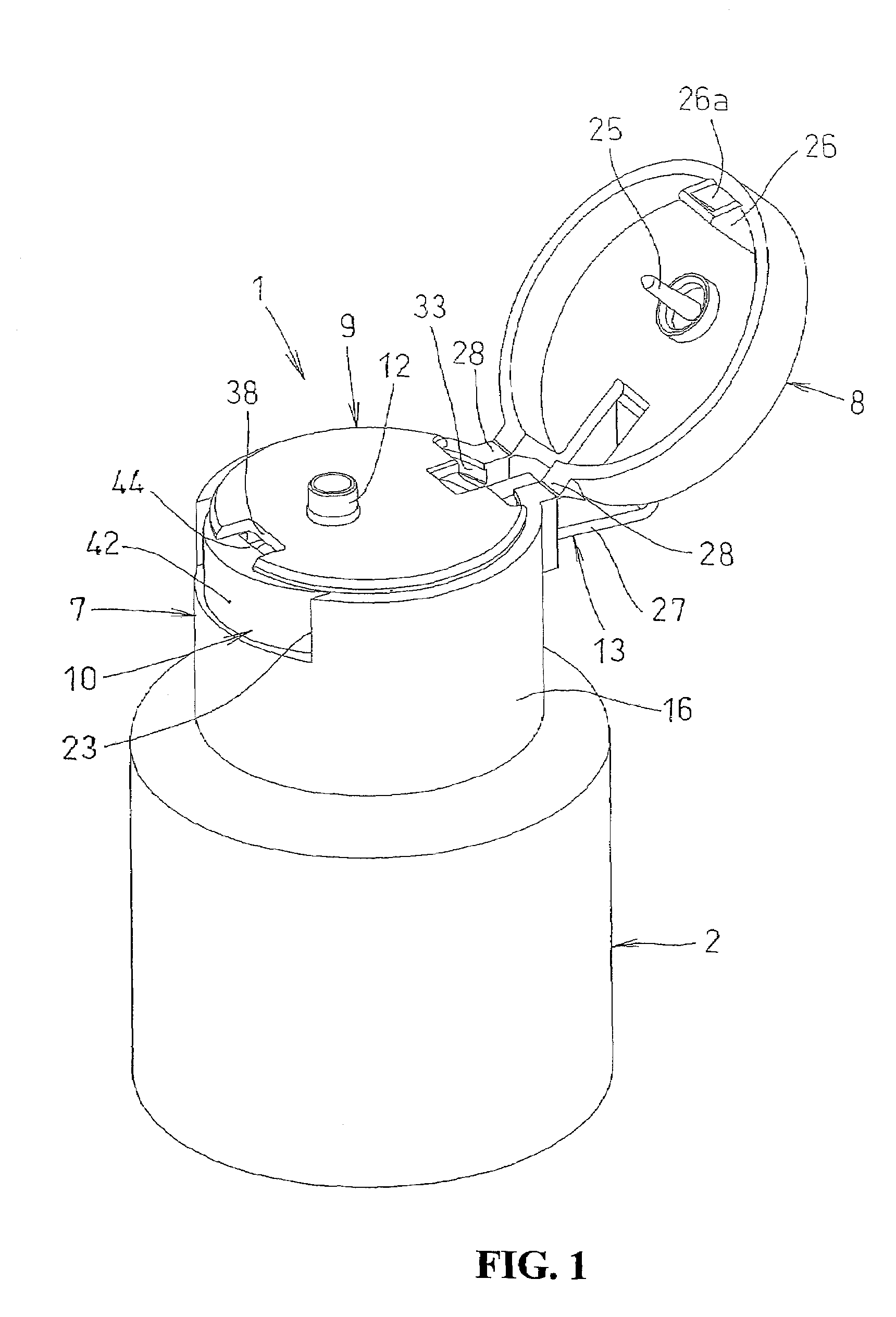
[0038]FIGS. 1 to 8 show a cap 1 according to one embodiment of the present invention.

[0039]In FIGS. 1 to 8, the cap 1 is detachably attached to a mouth 3 of a container main body 2 and a container such as a bottle for cosmetics is constituted by the container main body 2 and the cap 1.

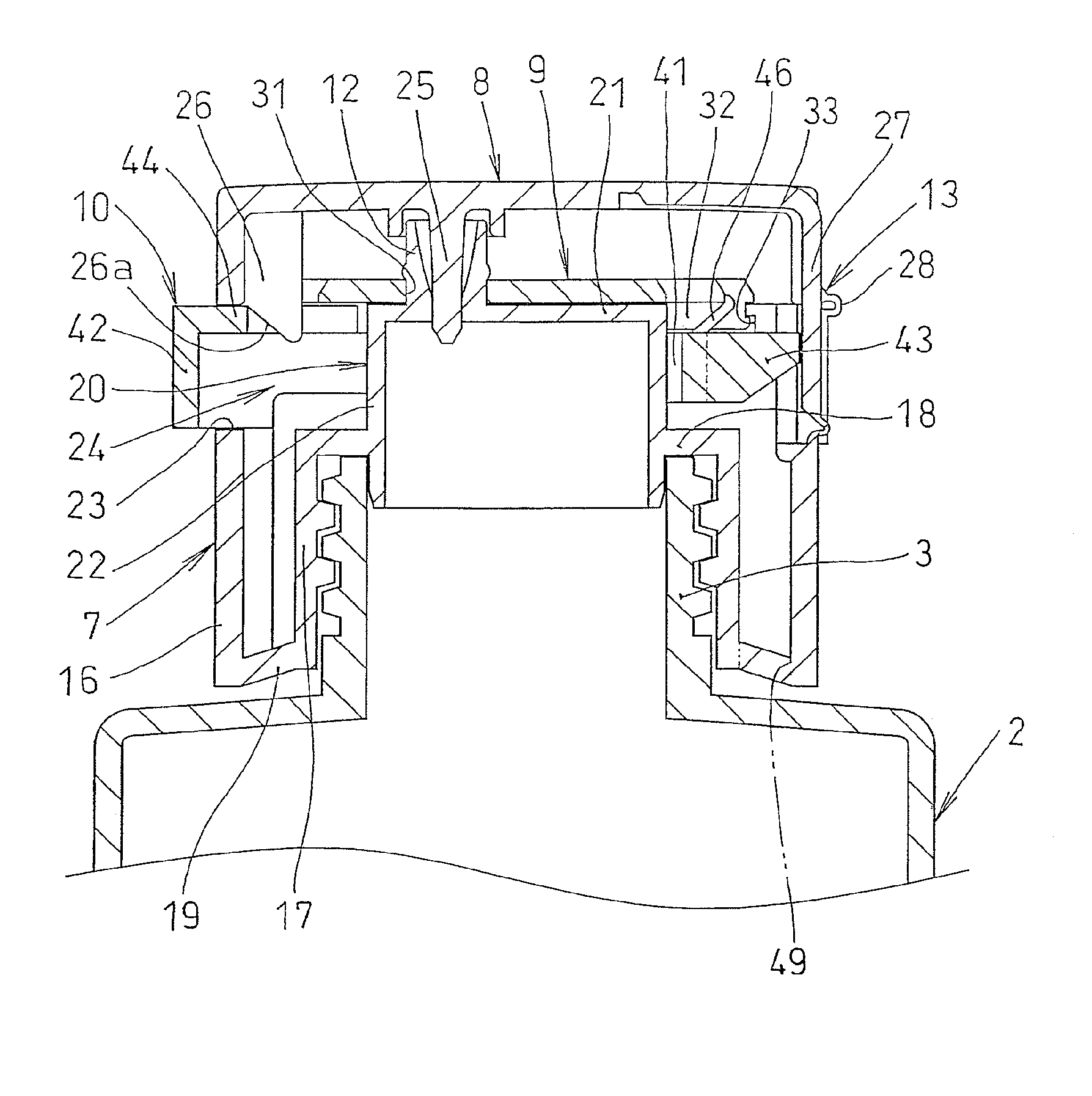
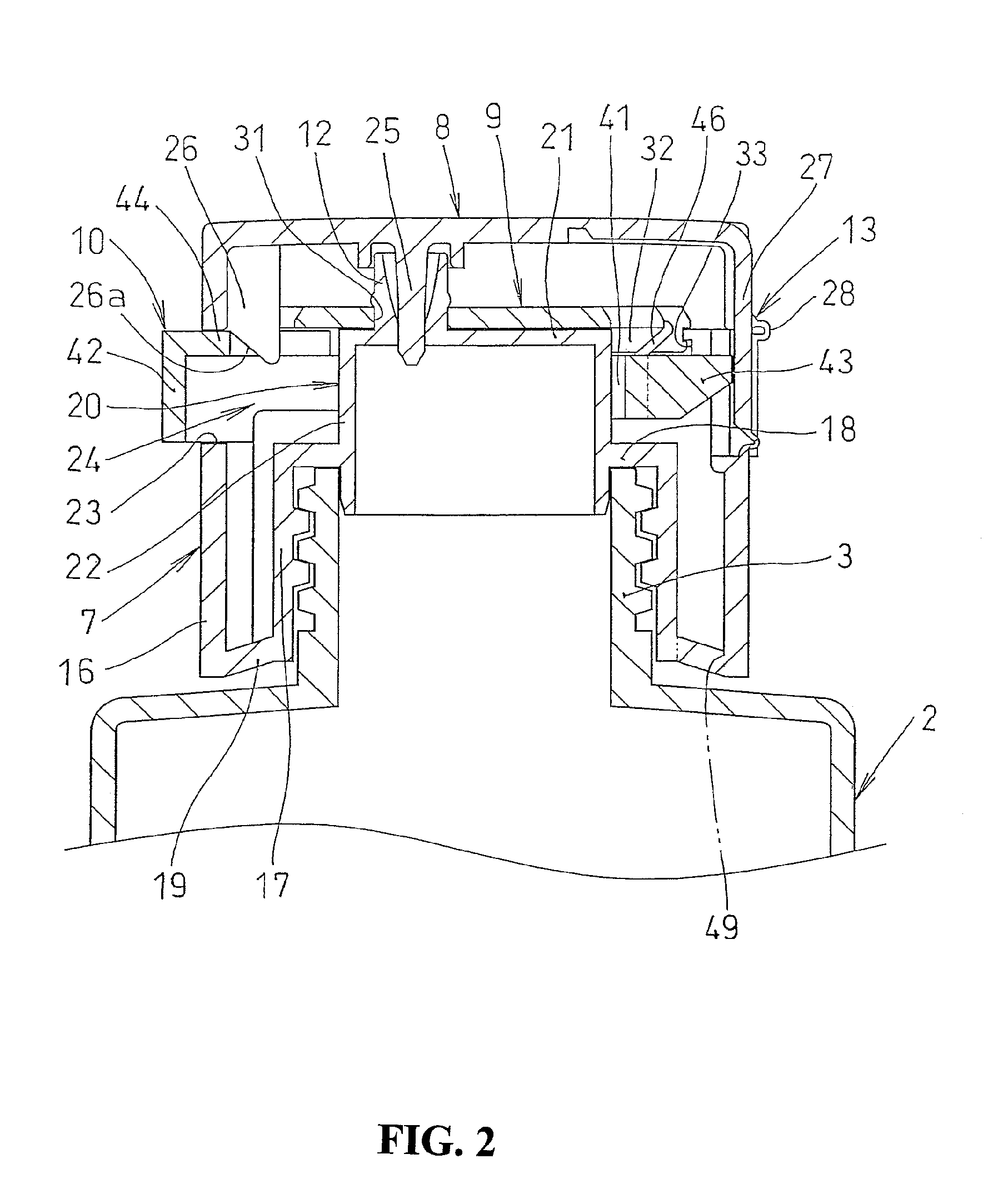
[0040]The cap 1 includes a cap main body 7 and a cap cover 8 that covers up a top portion of the cap main body 7. The cap 1 also includes a support 9 fixed to the cap main body 7 and a manipulation body 10 supported by the support 9. The cap main body 7 includes an outlet 12 attached to the mouth 3 of the container main body 2 and projecting upward. The cap cover 8 is connected to a rear end of the cap main body 7 via an opening / closing hinge 13 and configured to cover up the top portion of the cap main body 7 so as to be able to freely open or close the cap main body 7.

[0041]The cap main body 7, the cap cove...


PUM


Abstract

A cap is provided which can be smaller in number of constituent elements, easy to manufacture with simple assembly operation, and of which cap cover can be smoothly opened with one hand for a long period of time. In the cap configured so that a pressing portion presses an opening / closing hinge of the cap cover backward to swing the cap cover in an open direction when a manipulation portion is pressed, a manipulation body includes an elastic connection rod arranged on a side of an outlet below a support, the manipulation portion is provided on a front end of the elastic connection rod, the pressing portion is provided on a rear end of the elastic connection rod, and the manipulation body is connected to the support via a deformable connection piece so as to allow a longitudinal movement of the manipulation body relative to the support.

Description

BACKGROUND OF THE INVENTION[0001]1. Field of the Invention[0002]The present invention relates to a cap used in a container such as a bottle for cosmetics.[0003]2. Description of the Related Art[0004]As a cap used in a container such as a bottle for cosmetics, there is known a cap having a cap main body that is attached to a mouth of a container main body and that includes an outlet projecting upward and a cap cover connected to a rear end of the cap main body via an opening / closing hinge so as to be able to cover a top portion of the cap main body with the cap cover and to freely open or close the top portion of the cap main body.[0005]One conventional cap of this type is configured so that a manipulation body is provided on a top surface of the cap main body so as to be slidable longitudinally, a manipulation portion is provided on a front end of the manipulation body, and so that a pressing portion is provided on a rear end of the manipulation body. When a user presses the manipul...

Claims


Application Information

Patent Timeline
Patent Type & Authority Patents(United States)
IPC IPC(8): B65D43/26B65D43/16B65D51/18B65D41/02
CPCB65D47/0814B65D2251/205B65D2251/1066B65D2251/1041
Inventor YAMANAKA, YASUHIROFUJITA, TAKAHIRO
Owner M F V
Why Eureka
Try Eureka