Flat panel display manufacturing apparatus

a manufacturing apparatus and flat panel technology, applied in the manufacture of electrode systems, cold cathode manufacturing, electric discharge tube/lamp manufacture, etc., can solve the problems of arcing phenomenon, excessive small diameter of spray hole, increase in dry-etching apparatus manufacturing costs, etc., and achieve easy manufacturing and simplified structure

Inactive Publication Date: 2005-05-19
ADVANCED DISPLAY PROCESS ENG
View PDF22 Cites 130 Cited by
  • Summary
  • Abstract
  • Description
  • Claims
  • Application Information

AI Technical Summary

Benefits of technology

[0013] Therefore, the present invention has been made in view of the above problems, and it is an object of the present invention to provide a flat panel display manufacturing apparatus having a shower head, which has a simplified structure and is easy to manufacture.
[0014] It is another object of the present invention to provide a flat panel display manufacturing apparatus having a shower head which can eliminate generation of an arcing phenomenon around spray holes during etching.
[0015] It is still another object of the present invention to provide a flat panel display manufacturing apparatus having a shower head which can prevent warping at the center region of a spray plate thereof.
[0016] It is still another object of the present invention to provide a flat panel display manufacturing apparatus having a chamber which defines a symmetrical interior space in order to prevent a substrate from being unevenly processed due to spatial asymmetry.
[0017] It is still another object of the present invention to provide a flat panel display manufacturing apparatus having baffles, which can maintain constant flow rate of plasma regardless of exhaust units, thereby enabling even processing of a substrate.
[0018] It is yet another object of the present invention to provide a flat panel display manufacturing apparatus having a plasma shielding device, which can effectively protect a substrate pedestal from plasma.

Problems solved by technology

As shown in FIG. 1, the shower head, provided in the conventional dry-etching type apparatus, has a complicated structure wherein a plurality of diffusion plates 4 and 5 are mounted, resulting in an increase in manufacturing costs of the dry-etching apparatus.
Typically, the spray plate 6 is formed with hundreds to thousands of spray holes, and the diameter of the spray holes is excessively small, less than 1 mm, complicating processing of the spray holes.
In this case, if a specific region of the anodized aluminum is damaged by plasma and exposed to the outside, electric current is instantaneously concentrated on the exposed aluminum of the shower head body and the spray plate, causing an arcing phenomenon.
Such an arcing phenomenon, specifically, frequently occurs around the spray holes of the spray plate 6, causing damage to the spray holes and resulting in the necessity of periodic exchange of the spray plate 6.
However, due to the high price and difficult manufacturing process thereof, frequent exchange of the spray plate 6 disadvantageously increases the price of substrates being produced.
The spray plate having such an increased surface area, however, suffers from warping at the center region thereof, complicating even diffusion of a process gas.
This provides the chamber with an asymmetrical interior space about the substrate pedestals and generates uneven plasma flow inside the chamber, resulting in uneven processing of substrates.

Method used


Image

  • Flat panel display manufacturing apparatus
  • Flat panel display manufacturing apparatus
  • Flat panel display manufacturing apparatus

Examples


embodiment 1

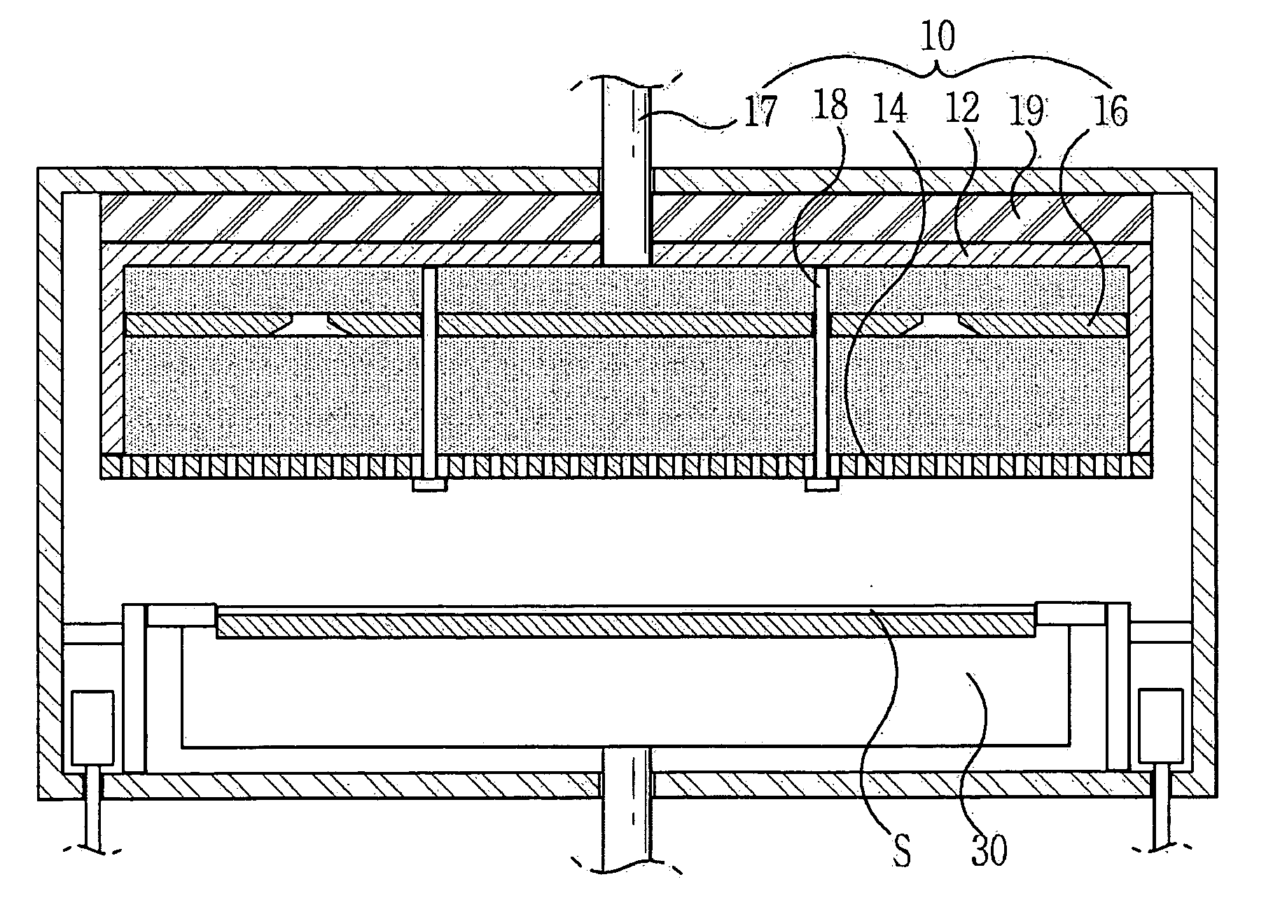
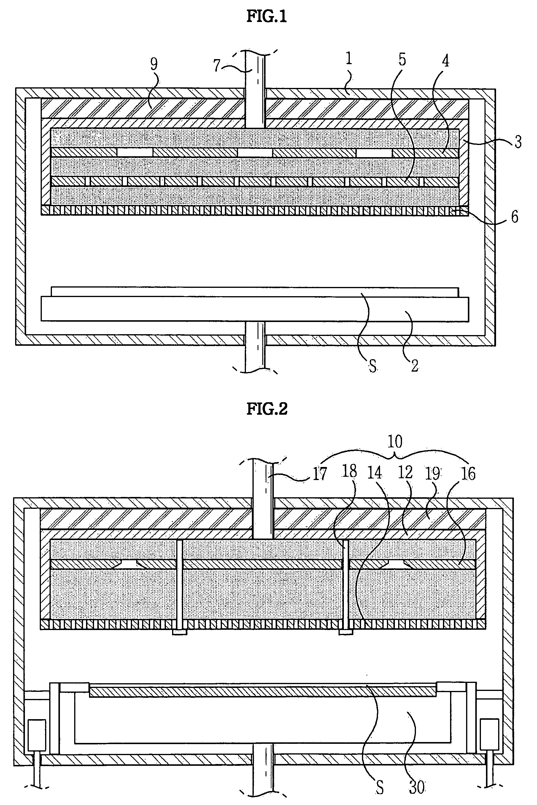
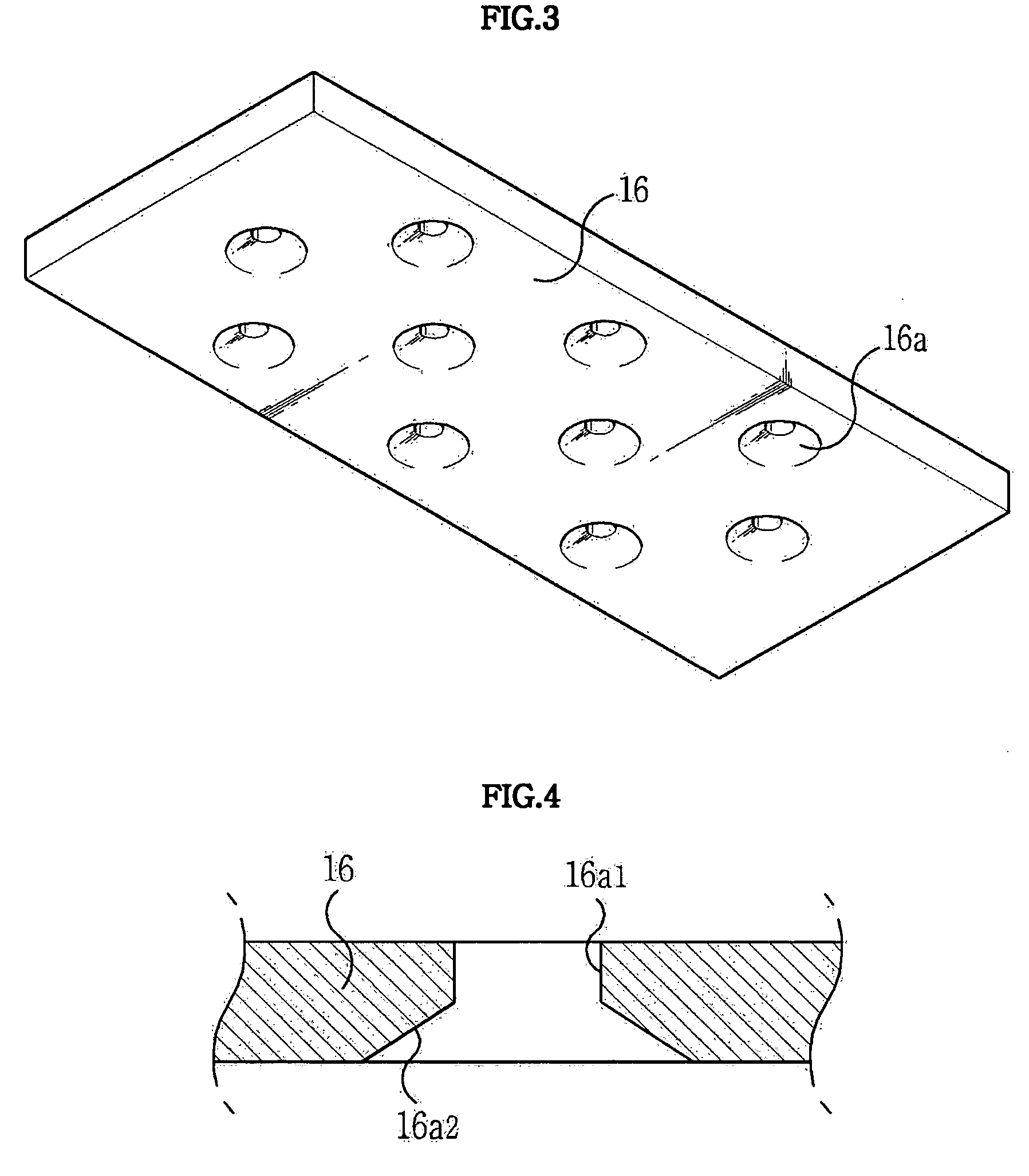
[0040]FIG. 2 is a sectional view illustrating the structure of a flat panel display manufacturing apparatus in accordance with the present invention. As shown in FIG. 2, the flat panel display manufacturing apparatus comprises a shower head 10, and in turn, the shower head 10 comprises: a shower head body 12, a diffusion plate 16, a spray plate 14, and spray plate supporting members 18.

[0041] The shower head body 12 of the shower head 10 is positioned in an upper portion of a chamber of the flat panel display manufacturing apparatus, and defines an interior space having a predetermined volume. The shower head body 12 is open at a lower surface thereof, and is fixedly attached at an upper surface thereof to a top wall surface of the chamber. At a predetermined position of the upper surface of the shower head body 12 is formed a process gas inlet channel 17 for introducing a process gas into the shower head body 12. An outer end of the process gas inlet channel 17 is coupled to an RF...

embodiment 2

[0052]FIG. 8 is a sectional view illustrating the structure of the chamber of the flat play display manufacturing apparatus in accordance with the present invention, in the chamber being defined an imaginary interior space for use in the generation of plasma. As shown in FIG. 8, the chamber of the flat panel display manufacturing apparatus is formed at one side wall thereof with a substrate entrance / exit opening 22. The flat panel display manufacturing apparatus of the present invention further comprises a gate valve 24 provided external to the substrate entrance / exit opening 22, and a shutter 26 provided internal to the substrate entrance / exit opening 22.

[0053] In this case, preferably, the shutter 26 is positioned so that an inner plane thereof coincides with an imaginary plane extending from an inner wall surface of the chamber. This serves to provide the chamber with a symmetrical interior space defined by a line 27 shown in FIG. 8. The symmetrical interior space of the chamber...

embodiment 3

[0062]FIG. 10 is an exploded perspective view illustrating the structure of a plasma shielding device in accordance with the present invention. The plasma shielding device of the flat panel display manufacturing apparatus comprises a horizontal shielding member 40 which consists of a plurality of pieces surrounding the edge of an upper surface of the substrate pedestal 30, and a vertical shielding member 50 which consists of a plurality of pieces surrounding the lateral surface of the substrate pedestal 30 as well as an imaginary surface extending downward from the lateral surface. The horizontal and vertical shielding members 40 and 50 are coupled so that they come into close contact with each other. Such a plasma shielding device is made of a plasma-resistant material, and preferred examples of the plasma-resistant material include ceramic, vespel, or the like.

[0063] It should be understood that the plasma shielding device of the present embodiment is commonly applicable to the s...


PUM

PropertyMeasurementUnit
diameteraaaaaaaaaa
diameteraaaaaaaaaa
diameteraaaaaaaaaa

Abstract

Disclosed herein is a flat panel display manufacturing apparatus in a predetermined process is performed using plasma generated therein. In such a flat panel display manufacturing apparatus, a process gas is supplied into a chamber in an evenly diffused state to generate even plasma inside a symmetrical interior space of the chamber. Consequently, the flat panel display manufacturing apparatus can appropriately control flow rate of the plasma, thereby being capable of performing even processing on a large-scale substrate. In the flat panel display manufacturing apparatus, a substrate pedestal thereof is provided with a combination of vertical and horizontal shielding members, thereby being entirely protected from attack of the plasma, resulting in an increased life-span.

Description

FIELD OF THE INVENTION [0001] The present invention relates to a flat panel display manufacturing apparatus which is capable of performing a predetermined process on a substrate under vacuum using plasma generated in the chamber. [0002] 1. Background of the Invention [0003] 2. Description of the Related Art [0004] In general, flat panel display manufacturing apparatuses are classified into wet-etching apparatuses using wet-chemical, and dry-etching apparatuses using inert gas. [0005] In such a dry-etching apparatus, a specific reactive gas is introduced into a strong electric field produced between two substrate pedestals, so that it is changed into an ionized plasma gas while being taken away electrons by the electric field. Here, the ionized plasma gas shows high reactivity in a neutral state. After that, using a byproduct produced as the plasma gas reacts with exposed regions of an oxide film not covered by a photoresist mask, the dry-etching apparatus performs a predetermined pr...

Claims


Application Information

Patent Timeline
Patent Type & Authority Applications(United States)
IPC IPC(8): B05B1/00C23C16/00C23F4/00H01J9/00H01J37/32H01L21/00H01L21/3065H05H1/00
CPCH01J37/3244
Inventor HUR, GWANG HOCHOI, JUN YOUNGLEE, CHEOL WONAHN, HYUN HWANHWANG, YOUNG JOOKIM, CHUN SIK
Owner ADVANCED DISPLAY PROCESS ENG
Why Eureka
Try Eureka