
Fixing arrangemenrt for a spring and/or damping element to a hollow support on a motor vehicle chassis

Inactive Publication Date: 2006-06-08
DAIMLER AG
View PDF9 Cites 8 Cited by
  • Summary
  • Abstract
  • Description
  • Claims
  • Application Information

AI Technical Summary

Benefits of technology

[0004] The object of the invention is to create a fixing arrangement of the type stated in the introductory part, by means of which the spring and / or damping element can be supported more rigidly and more stably on the hollow member of the motor vehicle body.
[0008] An especially rigid and stable attachment of the spring and / or damping element is obtained if an adapter plate, which when fitted is fastened to the socket of the spring and / or damping element with bracing and separating effect, is supported on the lower flange of the hollow member.
[0009] A further increase in rigidity in the area of the attachment of the spring and / or damping element to the hollow member is ensured in that a cage, which connects the upper flange and lower flange of the hollow member together whilst reinforcing the member cross-section, is provided between the socket and the adapter plate inside the hollow member.
[0010] In particular, the cage exercises an effect on the buckling rigidity of the hollow member if the cage is arranged in the area of an offset of the hollow member—for example, in proximity to the wheel housing or the axle of the motor vehicle.

Problems solved by technology

A disadvantage with this known fixing arrangement is that the distance between the wheel suspension member and the hollow member of the body is not susceptible to any enlargement, for example in order that a longer spring and / or damping element may be arranged between them.

Method used


Image

  • Fixing arrangemenrt for a spring and/or damping element to a hollow support on a motor vehicle chassis
  • Fixing arrangemenrt for a spring and/or damping element to a hollow support on a motor vehicle chassis
  • Fixing arrangemenrt for a spring and/or damping element to a hollow support on a motor vehicle chassis

Examples


Embodiment Construction

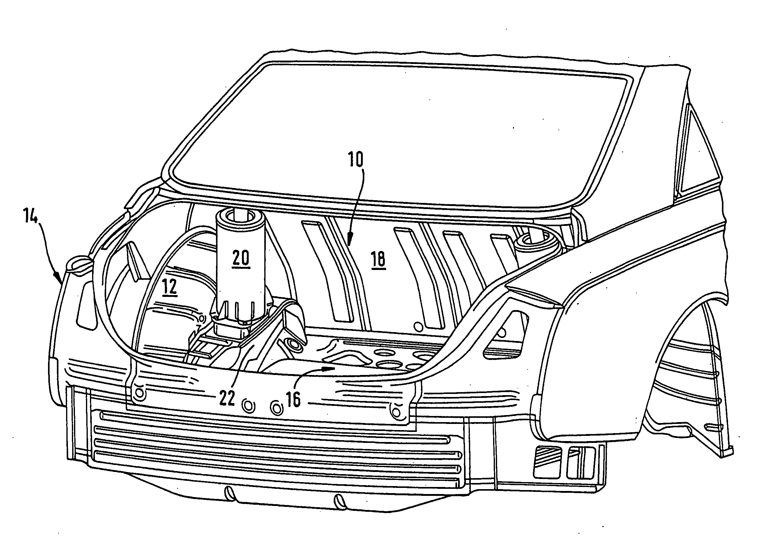
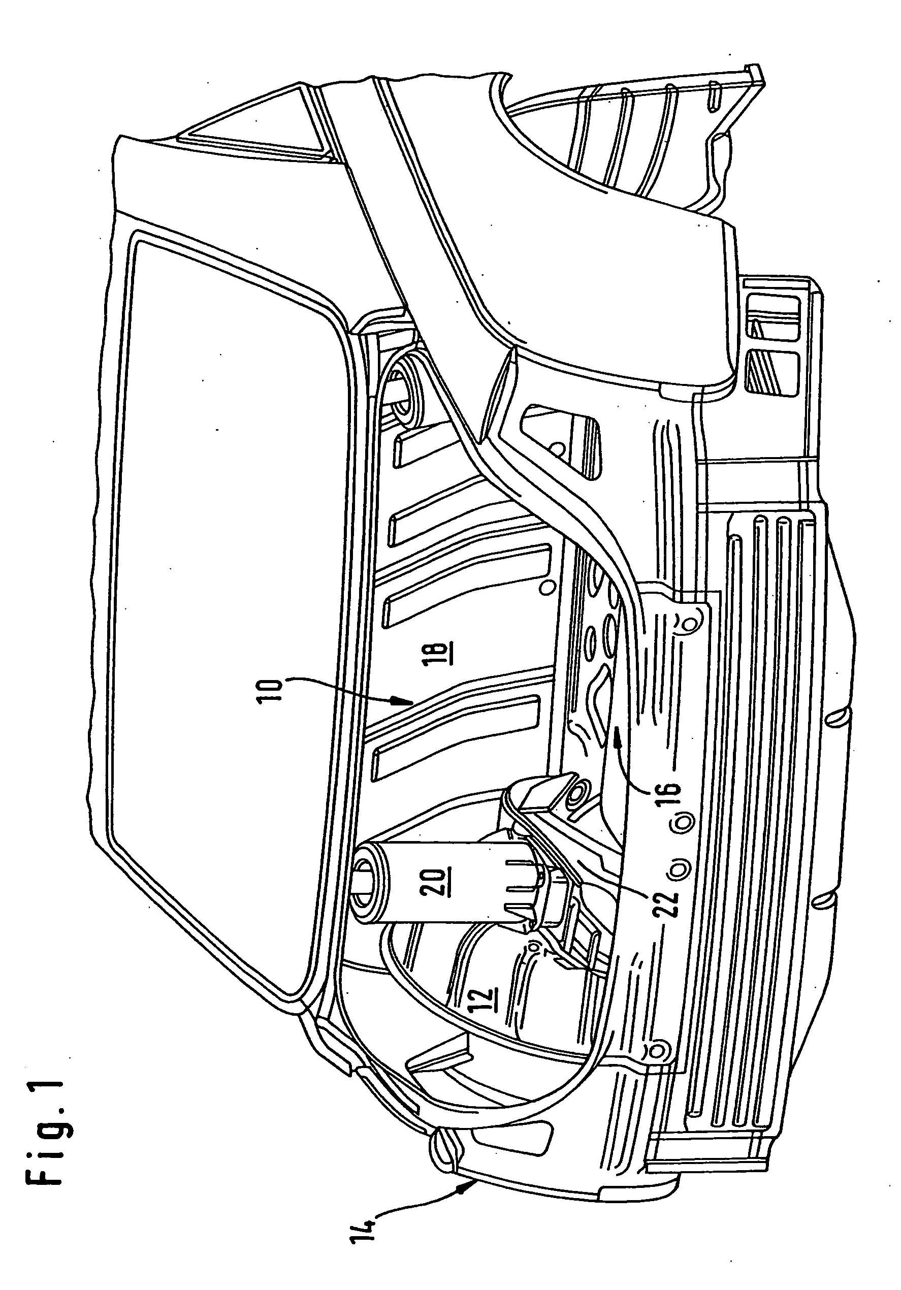
[0018]FIG. 1 shows a perspective view of the rear of a self-supporting motor vehicle body having a trunk 10, which is defined laterally by side walls 14 provided with wheel housings 12, at the bottom by a trunk floor 16 and at the front by a rear wall 18. A spring and damping element 20 of the pneumatic suspension of the motor vehicle is arranged inside each of the wheel housings 12, the elements each being fixed to an assigned rear side member 22 of the motor vehicle, as described further below.

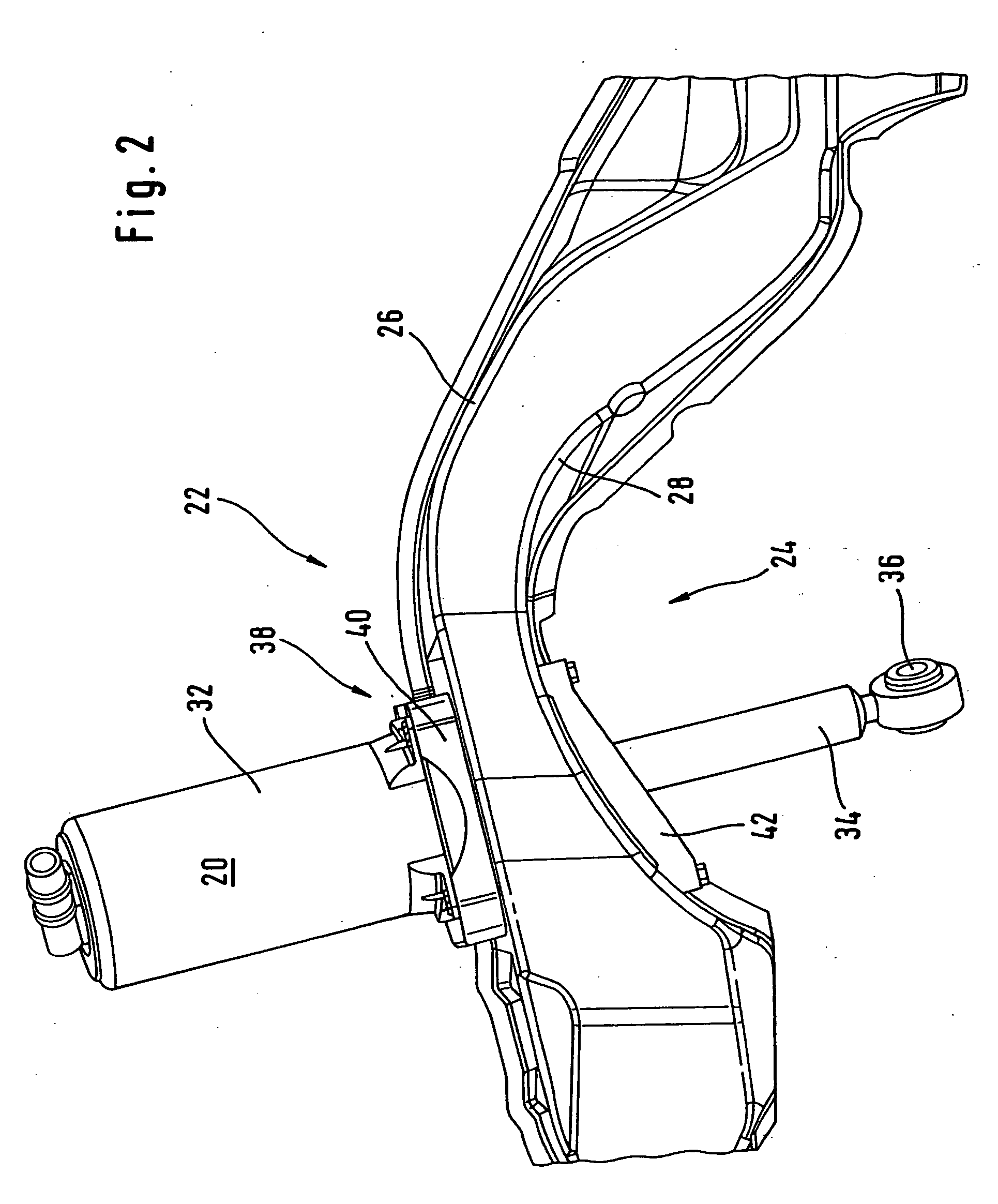
[0019]FIG. 2 shows a perspective, partial view of the fixing arrangement for fixing the spring and damping element 20 to the body rear side member 22. The side member 22 here takes the form of a continuous hollow member, which is composed, for example, of sheet metal shells welded together. The side member 22 here has an offset 24 in the area of the wheel housing 12 or a rear axle of the motor vehicle, not drawn in here.

[0020] Looking at FIG. 2 in conjunction with FIGS. 3 and 4, in which t...


PUM


Abstract

A fixing arrangement is provided for fixing a spring and / or damping element to a continuous hollow member of a motor vehicle body, into the lower flange of which a through-opening for the spring and / or damping element is let. The spring and / or damping element fixes a wheel suspension member of the motor vehicle to the hollow member by way of a load-distributing support. In order to support a longer spring and / or damping element against the hollow member of the motor vehicle body without increasing the distance from the wheel suspension member, the spring and / or damping element passes right through the hollow member and extends upwards from the upper flange of the hollow member. The spring and / or damping element is supported against the upper flange of the hollow member by a radially protruding socket. An adapter plate, which, when fitted, is fastened to the socket with a bracing and separating effect, is supported on the lower flange of the hollow member.

Description

BACKGROUND AND SUMMARY OF THE INVENTION [0001] This invention relates to the fixing arrangement for fixing a spring and / or damping element to a hollow member of a motor vehicle body. [0002] Each of U.S. Pat. Nos. 2,806,713 and 2,314,505 discloses a fixing arrangement for fixing a spring and / or damping element to a continuous hollow member of a motor vehicle body and in which a though-opening for the spring and / or damping element is let into a lower flange of the hollow member. In each of these cases the spring and / or damping element passes right through the hollow member and extends upwards out of the upper flange of the hollow member. A damper dome, which is supported on the hollow member by means of a radially protruding socket, is fixed to the upper flange as load-distributing support. [0003] German document DE 198 27 864 C1, furthermore, discloses a fixing arrangement, in which a through-opening, through which an upper end of a spring element projects into the hollow member, is ...

Claims


Application Information

Patent Timeline
IPC IPC(8): B60G7/02B62D17/00F16F9/00B60G13/00B60G15/06B62D25/08
CPCB60G13/003B60G15/067B62D25/088
Inventor BIRKWALD, OLIVIERSIKORSKI, JOERGWEBER, JENS
Owner DAIMLER AG
Learn More