Exercise machine for conditioning athletes

a technology for conditioning athletes and exercise machines, applied in the field of sports conditioning exercise machines, can solve the problems of not achieving the best results on the field of play, unable to promote the mastery of the muscles, and unable to use the explosive hip roll and drive motion described abov

Inactive Publication Date: 2006-04-18
FULLER SR BARNEY R
View PDF7 Cites 36 Cited by
  • Summary
  • Abstract
  • Description
  • Claims
  • Application Information

AI Technical Summary

Benefits of technology

[0017]It is therefore an object of the present invention to provide a exercise machine which aids a football player in perfecting the art of blocking.

Problems solved by technology

A strong athlete is not necessarily a powerful athlete and strength alone will not achieve the best results on the field of play.
While there are many devices which teach the art of blocking, none of these devices promotes the mastery of, or conditions the muscles in the manner utilized in the explosive hip roll and drive motions described above.

Method used


Image

  • Exercise machine for conditioning athletes
  • Exercise machine for conditioning athletes
  • Exercise machine for conditioning athletes

Examples


Embodiment Construction

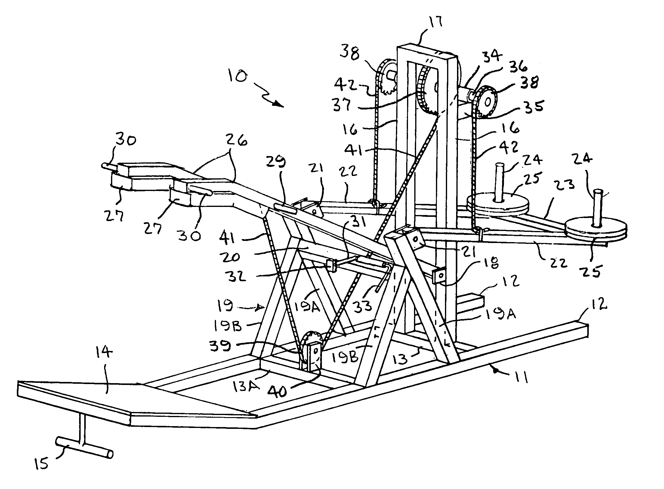
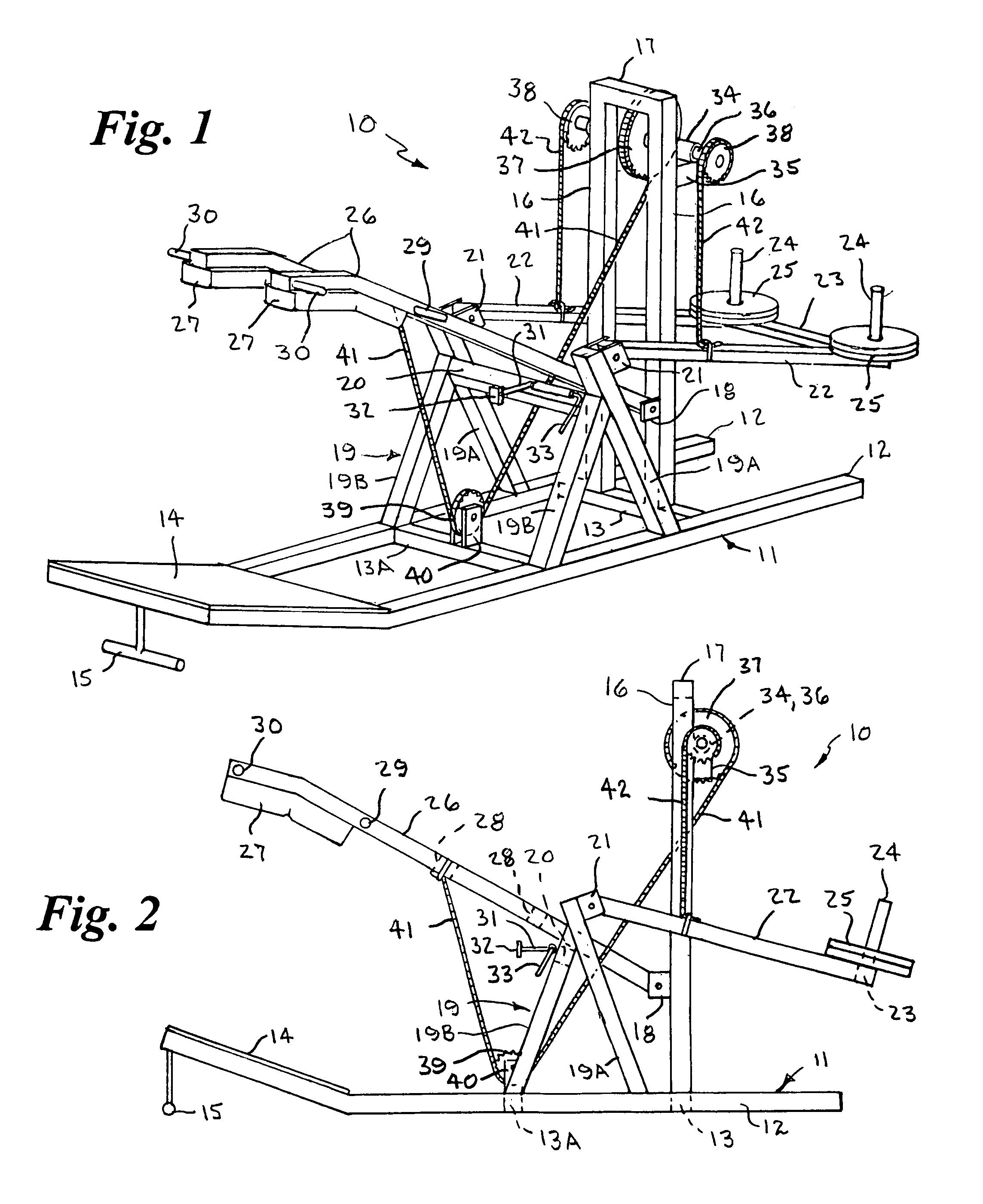
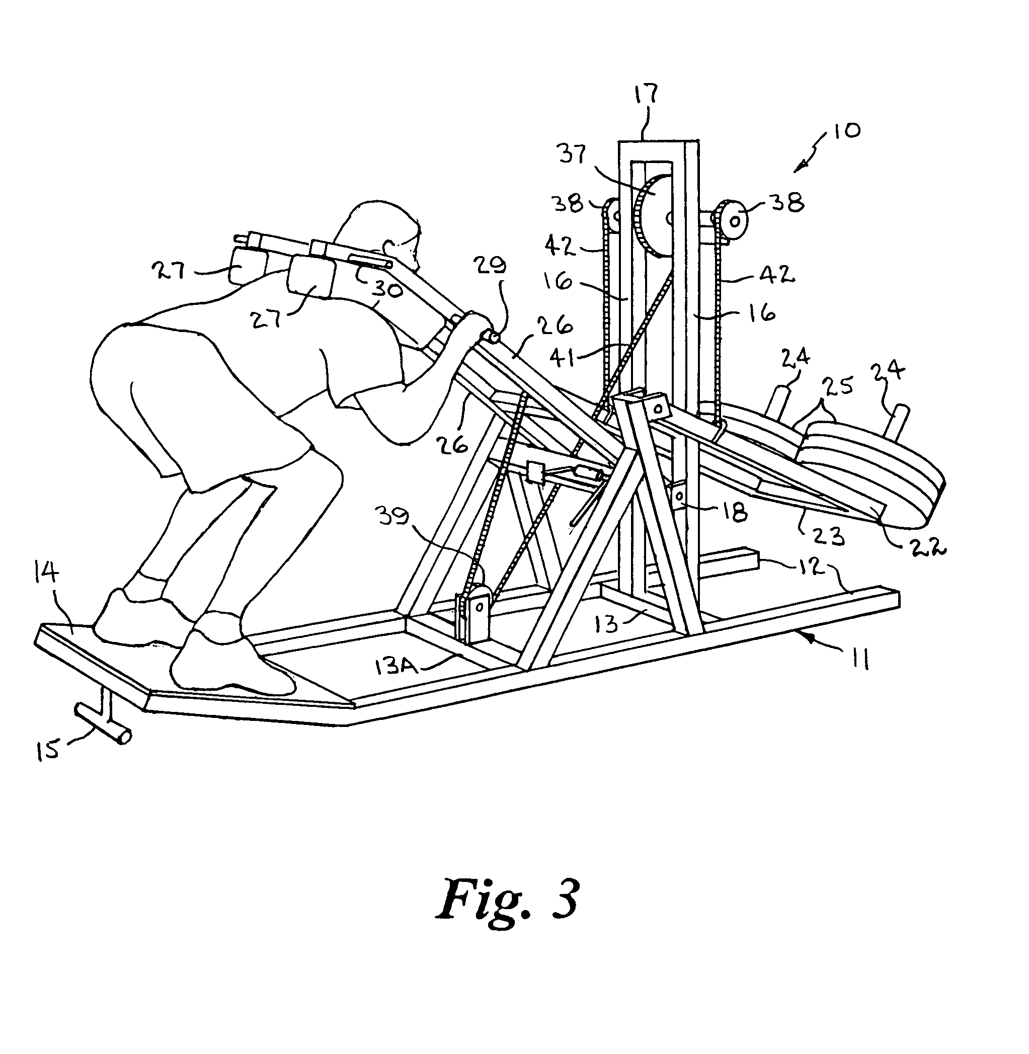
[0031]Referring to the drawings by numerals of reference, there is shown in FIGS. 1, 2, and 3, a preferred exercise machine 10 which develops the ability of an athlete, such as an offensive or defensive lineman, to smoothly and quickly pivot the upper body relative to the lower body by forcefully moving his hips in an explosive angularly upward roll and drive motion through a resistive weight load simulating an effective and powerful blocking movement, and strengthens the gluteus, quadriceps, and hamstring muscle areas.

[0032]The exercise machine 10 comprises a frame 11 having a pair of elongate parallel spaced base members 12 of square tubing. One or more cross members 13 are secured transversely between the base members 12 at longitudinally spaced locations. A foot platform 14 of flat plate is secured to the top of the base members 12 at a rearward end to extend transversely therebetween and provide a surface upon which the athlete stands. The rearward end of the base members 12 an...


PUM


Abstract

An exercise machine has a frame with a generally rectangular base and a platform disposed at an angle at one end upon which the user stands. A horizontal shaft rotatably mounted on a pair of vertical frame members near the forward end of the base has an upper central sprocket at its center and smaller sprockets at its outer ends. A lower central sprocket is rotatably mounted on the base. A weight support arm pivotally connected to a pair of upright frame members extends forwardly therefrom and a selected number of weights are received on the outer end thereof. An elongate lift arm pivotally connected to the vertical frame members extends angularly upward and rearward therefrom toward the platform and has a pair of shoulder pads at its outer end positioned a distance above the platform, with a first and second pair of lateral hand grips near each end of the pads for griping the bar in two positions. A first chain wrapped around the upper central sprocket extends under the lower central sprocket and has its free end connected to the lift arm and a pair of second chains each wrapped around an outer sprocket in the opposite direction have their free ends connected to the weight supporting member. When the lift arm is raised by an upward force on the shoulder pads and/or hand grips, the lift arm pivots upward pulling the first chain down causing rotation of the upper central sprocket and outer sprockets which causes the second chains to pivot the weight supporting member upward with the weights at the outer ends thereof resisting the upward force applied to the lift arm.

Description

CROSS REFERENCE TO RELATED APPLICATION[0001]This application claims priority of U.S. Provisional Application Ser. No. 60 / 444,516 iled Feb. 3, 2003.BACKGROUND OF THE INVENTION[0002]1. Field of the Invention[0003]This invention relates generally to the field of sports conditioning exercise machines, and more particularly to an exercise machine for conditioning athletes to pivot the upper body relative to the lower body by forcefully moving the hips in a roll and drive motion upwardly through a resistive weight load.[0004]2. Background Art[0005]In the sport of football, the most effective way to block an opposing player is to advance toward the opponent while moving horizontally in a crouched position, and upon making contact with the opponent, to exert an explosive force vertically upward on the opponent which tends to lift the opponent off the ground. The player doing the blocking must smoothly and quickly pivot the upper body relative to the lower body by forcefully moving his hips ...

Claims


Application Information

Patent Timeline
Patent Type & Authority Patents(United States)
IPC IPC(8): A63B71/06
CPCA63B21/0615A63B21/08A63B21/1469A63B21/151A63B23/03525A63B23/0405A63B21/1492A63B2023/0411A63B21/4035A63B21/4047
Inventor FULLER, SR., BARNEY R.
Owner FULLER SR BARNEY R
Why Eureka
Try Eureka