
Multi-degree of freedom transducer

a transducer and degree technology, applied in the direction of instruments, force measurement, force/torque/work measurement apparatus, etc., can solve the problems of difficult replacement of transducer elements, complex moving parts, and difficult positioning

Active Publication Date: 2013-03-21
GENERAL ELECTRIC CO
View PDF7 Cites 6 Cited by
  • Summary
  • Abstract
  • Description
  • Claims
  • Application Information

AI Technical Summary

Benefits of technology

The proposed transducer can be used in medical applications and can sense wrist motion without needing to move parts. This means that less attention and time is needed for manipulation, which is beneficial for medical procedures.

Problems solved by technology

In such proposed systems, one of the common problems is that a number of joysticks or buttons are necessary to enable six degrees of freedom positioning, making the positioning difficult.
An operator has to observe the motions of the controlled object, i.e. a visual feedback is necessary which is highly disadvantageous in medical applications where often quick actions are necessary.
Furthermore, the joystick-like controllers involve complex moving parts, difficult replacement of the transducer elements, and some systems do not provide six degrees of freedom sensing.
This is not really possible with moveable controllers, e.g. joysticks.
The known controllers do not allow their use in such situations, as they can not be properly actuated if they are not or are hardly visually locatable.
This optical measurement is not suitable for the above intended purposes.
Moving, parts have the drawbacks above and are more sensitive to dust and contamination.

Method used


Image

  • Multi-degree of freedom transducer
  • Multi-degree of freedom transducer
  • Multi-degree of freedom transducer

Examples


Embodiment Construction

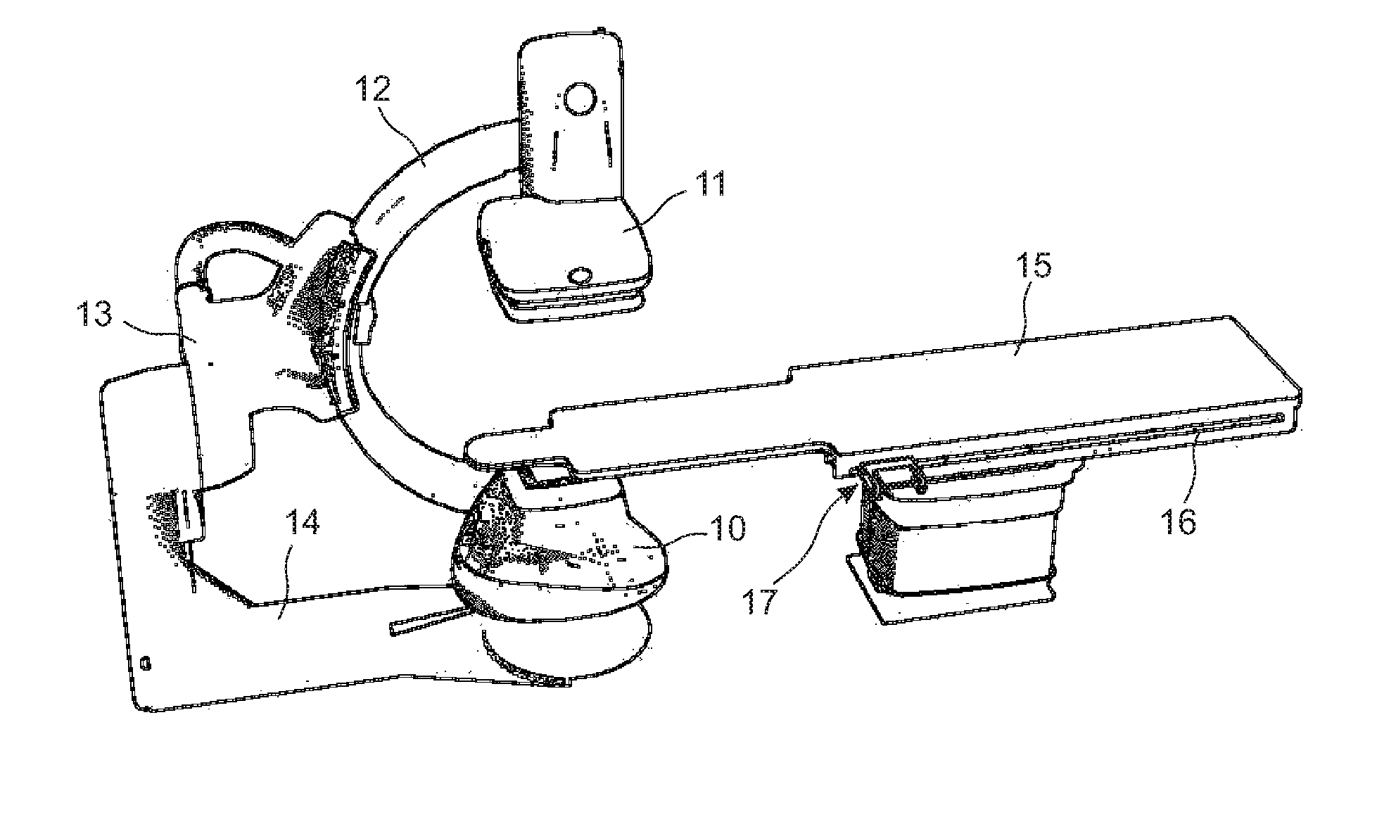
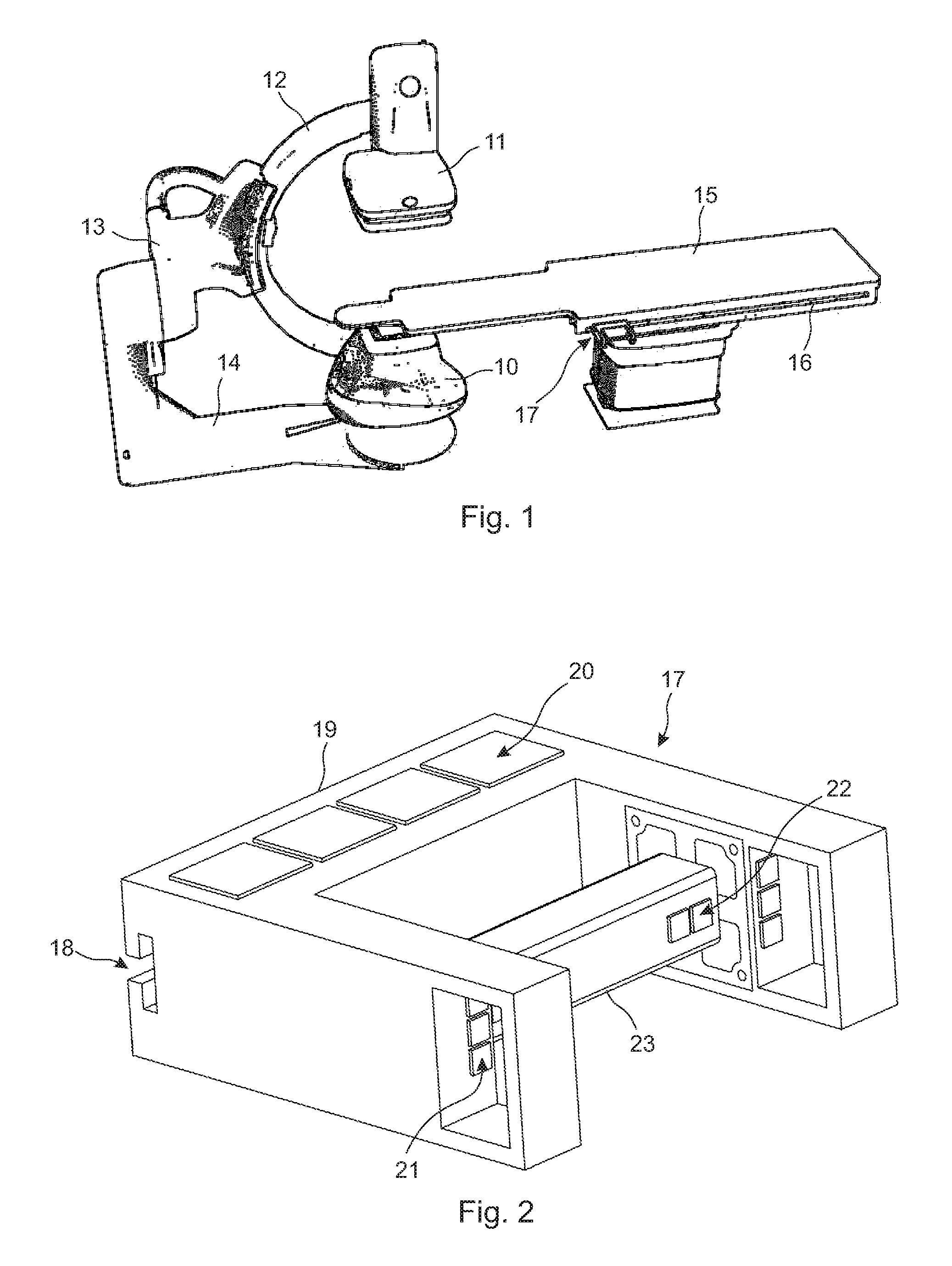
[0019]Referring first to FIG. 1, an X-ray apparatus is schematically shown for which the transducer can be used. The X-ray apparatus comprises an X-ray emitter 10 and a detector 11 which are connected with each other by a C-arm 12. The C-arm 12 is mounted onto a pivot 13; the C-arm 12 can be moved along its arc by means of an electromechanical drive in the pivot 13. The pivot 13 is rotatably mounted onto an end of an L-arm 14; the pivot 13 can be rotated around a horizontal axis by means of another electromechanical drive. The other end of the L-arm 14 is fixed in a rotatable way and is rotatable around a vertical axis by means of a further electromechanical drive. All the above mentioned parts are called together as a gantry. The structure of the gantry enables adjustment of the direction of the X-ray beam b means of moving together the X-ray emitter 10 and the detector 11 in six degrees of freedom.

[0020]The X-ray apparatus also comprises a table 15 which is also movable and rotata...


PUM

PropertyMeasurementUnit
angleaaaaaaaaaa
degrees of freedomaaaaaaaaaa
thickaaaaaaaaaa

Abstract

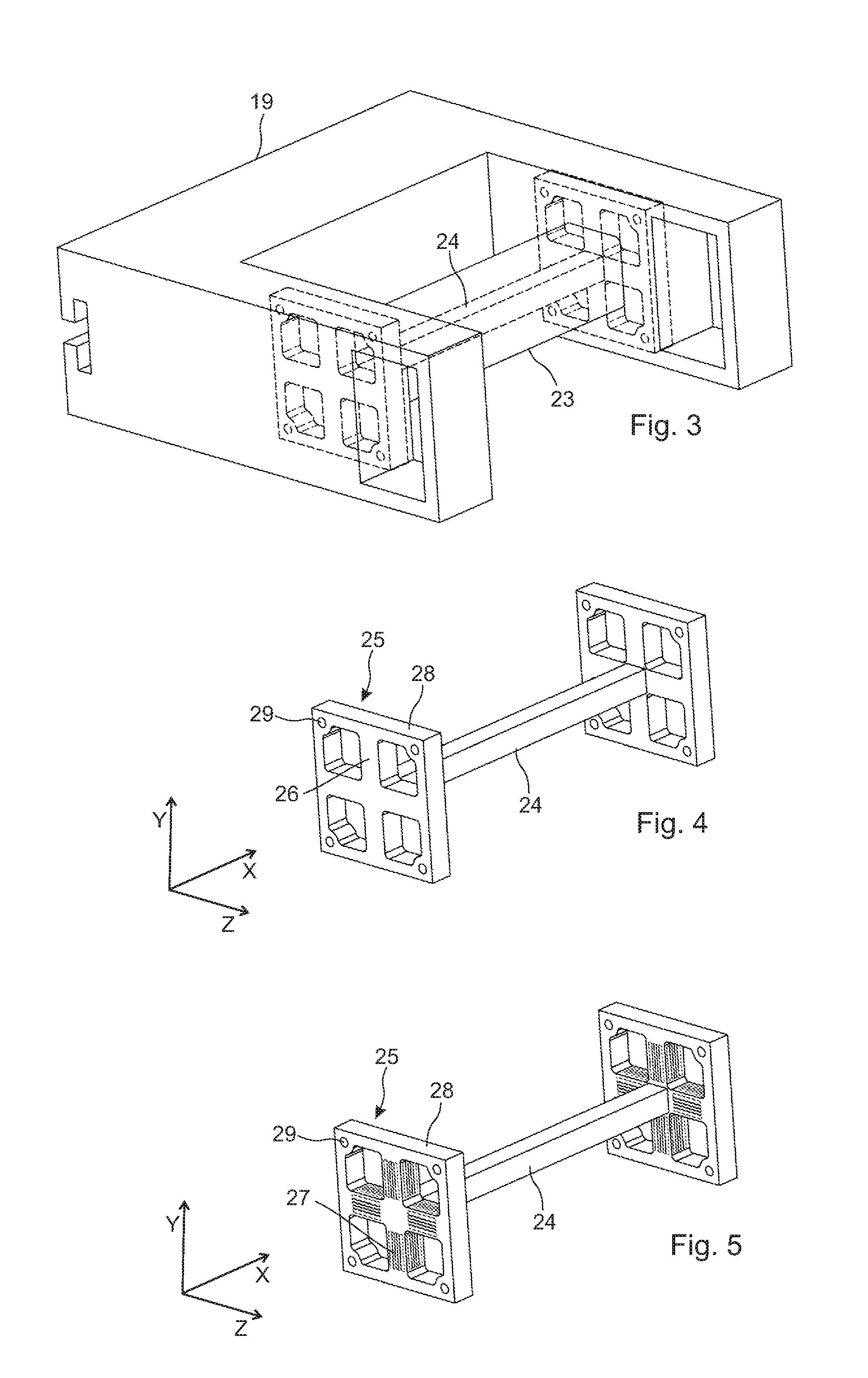
A multi-degree of freedom transducer for converting manually applied forces and torques into electrical signals, and configured to be fixed to a base object. The transducer comprises a handle bar having two ends and a first longitudinal direction, and a supporting assembly suitable for fixing the two ends of the handle bar to the base object. The supporting assembly comprising a frame structure at each of the ends of the handle bar, wherein each of the frame structures comprises at least two measuring beams. At least one of the measuring beams includes a second longitudinal direction and at least one other of the measuring beams includes a third longitudinal direction Each of the at least two measuring beams comprises two strain gauges configured to sense strain in the third longitudinal direction and arranged on two different, non-parallel side surfaces of each of the at least two measuring beams.

Description

BACKGROUND OF THE INVENTION[0001]The subject matter disclosed herein relates to a multi-degree of freedom transducer for converting manually applied forces and / or torques into electrical signals, and more particularly, to a six degrees of freedom transducer for a medical tableside user interface enabling motion-control of mechanical and / or virtual components.[0002]In medical applications it is often necessary to position a patient with respect to an external x-ray or radiotherapy beam. In the field of radiotherapy and X-ray imaging the irradiation of beams requires very high precision, it is therefore of prime importance to position the patient correctly with respect to the radiation. In radiotherapy and X-ray imaging, the patient is generally placed on a table and then the table and / or the X-ray device is positioned using electromechanical equipment.[0003]In recent years, there have been proposed joystick-like or button-based manipulators to perform mechanical positioning in medica...

Claims


Application Information

Patent Timeline
Patent Type & Authority Applications(United States)
IPC IPC(8): G01L1/22
CPCG01L5/223G01L5/161G01L1/2225G01L5/1627
Inventor SIKLOS, NORBERTCZUPI, BALINTKRIZSAN, NORBERTBEKY, ZSOFIA
Owner GENERAL ELECTRIC CO
Learn More