Field sequential display of color video picture with color breakup prevention

a color video and color breakup technology, applied in the field of color video picture color breakup prevention, can solve the problems of observer discomfort and fatigue, liquid crystal display apparatus not being able to make full use of the resolution of the liquid crystal display device used, and large and expensive liquid crystal display apparatuses to manufacture. , to achieve the effect of preventing color breakup

Inactive Publication Date: 2006-05-09
VISTA PEAK VENTURES LLC
View PDF10 Cites 46 Cited by
  • Summary
  • Abstract
  • Description
  • Claims
  • Application Information

AI Technical Summary

Benefits of technology

[0016]It is therefore an object of the present invention to provide a method of and an apparatus for displaying a color video picture based on the field sequential display principles while preventing color breakups from occurring and being visually perceived.

Problems solved by technology

However, the liquid crystal display apparatus fails to make full use of the resolution of the liquid crystal display device used because the number of picture elements of a video picture displayed by the liquid crystal display apparatus is one-third of the number of pixels of the liquid crystal display device.
However, the liquid crystal display apparatus is large and expensive to manufacture because the liquid crystal display devices for generating the three color primary images are required and an optical system is needed for color separation and color combination.
However, the above field sequential color display apparatus suffer a problem in that since achromatic images such as white (W) images and images of intermediate colors are represented by a temporal combination of R, G, B images, if the observer abruptly moves its line of sight while a white dot or object, for example, is being displayed, then the R, G, B images formed on the retina are displaced, and their colors R, G, B fail to be mixed into white, but are perceived as being separated from each other.
This phenomenon gives an instantaneous strong stimulus in the form of flickering primary color lights to the observer, making the observer feel uncomfortable and fatigued.
The burden on the display device is too large for the reduction of the color breakup that is achieved.

Method used


Image

  • Field sequential display of color video picture with color breakup prevention
  • Field sequential display of color video picture with color breakup prevention
  • Field sequential display of color video picture with color breakup prevention

Examples


1st embodiment

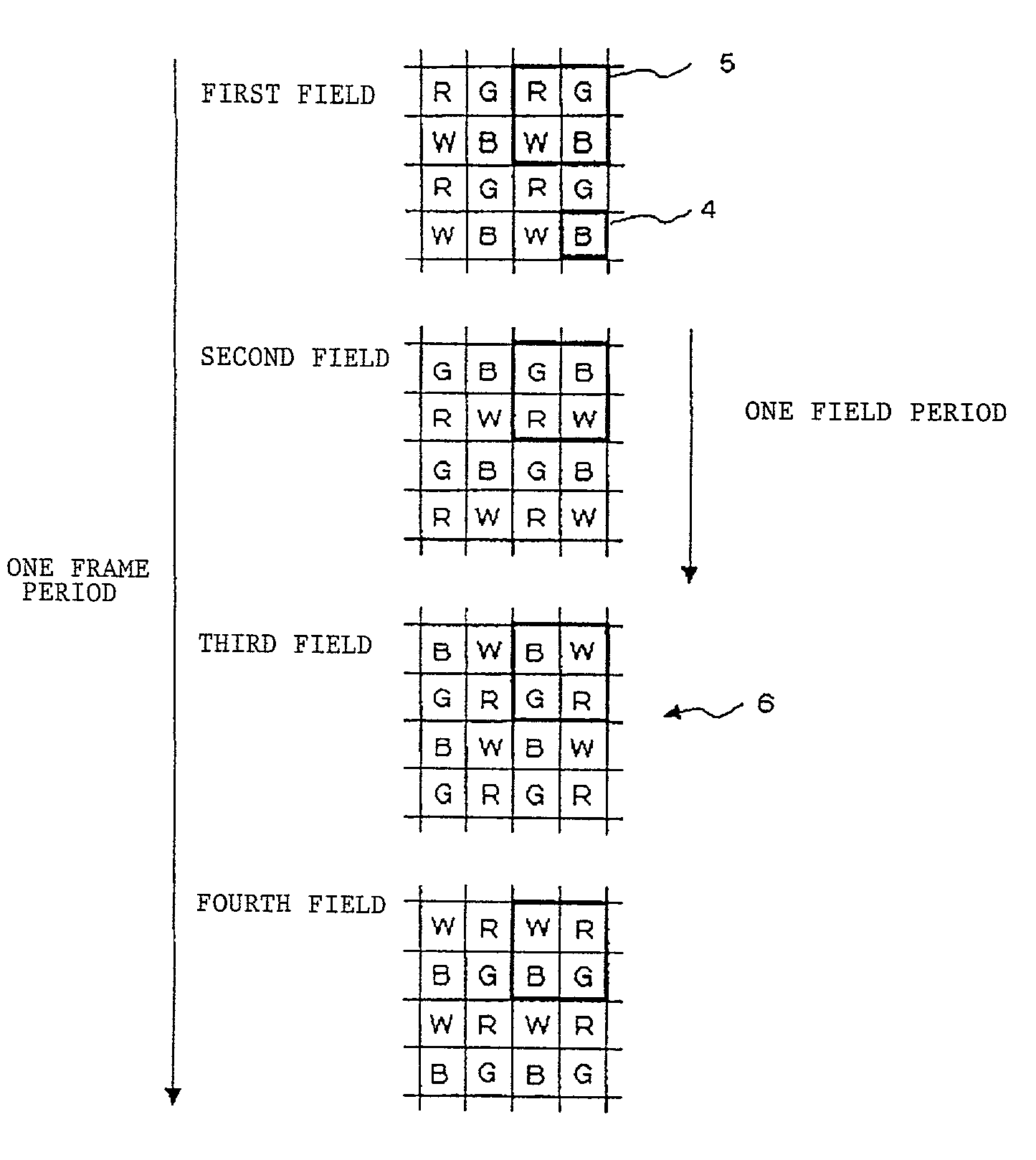
[0040]FIG. 4 shows at an enlarged scale a temporal succession of displayed images, illustrative of a display process according to a first embodiment of the present invention. As shown in FIG. 4, a matrix of pixels 4 is arrayed in displayed image 6 on a display device. One frame of image is composed of four fields of image including first through fourth fields. A set of adjacent four pixels in the matrix of pixels 4 is handled as a unit 5 in the form of a square matrix. Illuminating lights applied to the respective four pixels of picture element 5 have respective colors different from each other, and the arrangement of colors in each unit 5 is cyclically changed in successive four fields. Information representing separate colors R, G, B, W based on a video signal is displayed in pixels 4 at positions and times corresponding to the colors of the illuminating lights applied to pixels 4, successively in fields of image. If the frequency of frames is 60 Hz (one frame period is about 16.7...

3rd embodiment

[0050]FIG. 7 shows, partly in block form, a color video picture display apparatus according to a third embodiment of the present invention. As shown in FIG. 7, the color video picture display apparatus comprises display device 1, color switching illumination unit 2, video signal processor 3, and projecting unit 9. Display device 1, color switching illumination unit 2, and video signal processor 3 of the color video picture display apparatus according to the third embodiment are identical to those of the color video picture display apparatus according to the second embodiment. The color video picture display apparatus according to the third embodiment differs from the color video picture display apparatus according to the second embodiment in that it additionally has projecting unit 9 for projecting video pictures displayed on display device 1.

[0051]Projecting unit 9 is a projection lens assembly comprising a plurality of lenses for projecting a video picture displayed on display dev...

6th embodiment

[0066]A color switching illumination unit according to a sixth embodiment which is applicable to the second and third embodiments will be described below.

[0067]FIG. 12 shows, in partially enlarged perspective, display device 1 and color switching illumination unit 52 according to the sixth embodiment. Color switching illumination unit 52 has a plurality of light-emitting regions 50 each associated with one pixel 4 of display device 1 for emitting illuminating light 56 which is either a red illuminating light, a green illuminating light, a blue illuminating light, or an achromatic illuminating light. A set of adjacent four pixels in the matrix of pixels of display device 1 is handled as a unit, and the colors of illuminating lights 56 applied from color switching illumination unit 52 to pixels 4 are different from each other. Color switching illumination unit 52 also has a moving means for moving the relative position of color switching illumination unit 52 and display device 1 by on...


PUM

PropertyMeasurementUnit
field frequencyaaaaaaaaaa
frequencyaaaaaaaaaa

Abstract

A method of displaying a color video picture according to a field sequential process is provided. A display device displays an image comprising a matrix of pixels. One frame image is composed of four field images ranging from a first field image to a fourth field image. With four adjacent pixels handled as one unit, the colors R, G, B, W of illuminating lights applied to the pixels in each unit are different from each other, and the arrangement of the colors is successively switched or changed in each field period. Information representing the colors R, G, B, W separated from a video signal is displayed sequentially in successive fields at positions corresponding to the colors of the illuminating lights applied to the pixels and times at which the illuminating lights are applied to the pixels.

Description

BACKGROUND OF THE INVENTION[0001]1. Field of the Invention[0002]The present invention relates to a method of and an apparatus for displaying a color video picture by sequentially displaying color images on a display device and switching illumination light colors depending on the displayed color images.[0003]2. Description of the Related Art[0004]Various different processes are employed to display color video pictures on display devices such as liquid crystal display devices. For displaying a color video picture on a direct-view-type liquid crystal display apparatus, red (R), green (G), and blue (B) microcolor filters are associated with pixels arranged in a matrix to pass either one of R, G, B lights separated from white light emitted by a back light source with respect to each of the pixels, and the transmittance of the liquid crystal is modulated with a video signal at each of the R, G, B pixels. The full color display of each picture element, which is composed of three R, G, B pi...

Claims


Application Information

Patent Timeline
Patent Type & Authority Patents(United States)
IPC IPC(8): H04N9/475G02F1/13G02F1/133G02F1/1335G02F1/13357G02F1/1343G09F9/00G09F9/30G09G3/20G09G3/34G09G3/36H04N5/74H04N9/12H04N9/31
CPCH04N9/3114G09G3/3413H04N9/3197H04N5/7441G09G2310/0235
Inventor IMAI, MASAO
Owner VISTA PEAK VENTURES LLC
Why Eureka
Try Eureka